
Page 70 -
P. 70
System Hydraulics
~L
5O ft.
Tank 'B'
NNN
~r
t.
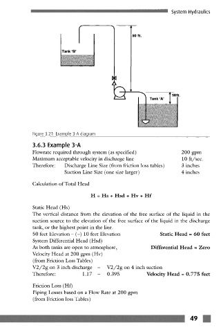
Figure 3.21: Example 3-A diagram
3.6.3 Example 3-A
Flowrate required through system (as specified) 200 gpm
Maximum acceptable velocity in discharge line 10 ft/sec.
Therefore: Discharge Line Size (from friction loss tables) 3 inches
Suction Line Size (one size larger) 4 inches
Calculation of Total Head
H = Hs + Hsd + Hv + Hf
Static Head (Hs)
The vertical distance from the elevation of the free surface of the liquid in the
suction source to the elevation of the free surface of the liquid in the discharge
tank, or the highest point in the line.
50 feet Elevation- (-) 10 feet Elevation Static Head = 60 feet
System Differential Head (Hsd)
As both tanks are open to atmosphere, Differential Head = Zero
Velocity Head at 200 gpm (Hv)
(from Friction Loss Tables)
V2/2g on 3 inch discharge - V2/2g on 4 inch suction
Therefore: 1.17 - 0.395 Velocity Head = 0.775 feet
Friction Loss (Hf)
Piping Losses based on a Flow Rate at 200 gpm
(from Friction loss Tables)
m
" T J m