
Page 64 -
P. 64
System Hydraulics
must be capable of handling the same Flow Rate as the larger pump.
Only the Head is being changed.
The ultimate example of Series Operation is the multistage pump where
the first impeller pumps into the second and then the third, etcetera.
This results in a high pressure pump with all the impellers operating at
the same capacity.
3.5.5.2 Parallel operation
In the more common Parallel
Operation, banks of pump are
used in parallel where they all take
their suction from a common
header and discharge into a
common header. Each of the two I i
(or more) pumps operates at the
same Head, but share the Flow
Rate.
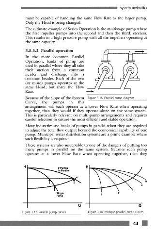
Because of the slope of the System Figure 3.16 Parallel pump diagram
Curve, the pumps in this
arrangement will each operate at a lower Flow Rate when operating
together, than they would if they operate alone on the same system.
This is particularly relevant on multi-pump arrangements and requires
careful selection to ensure the most efficient and stable operation.
Many industries use banks of pumps in parallel when they are required
to adjust the total flow output beyond the economical capability of one
pump. Municipal water distribution systems are a prime example where
such flexibility is required.
These systems arc also susceptible to one of the dangers of putting too
many pumps in parallel on the same system. Because each pump
operates at a lower Flow Rate when operating together, than they
_• 2 Pumps
f
5
Single 1 2
Pump
Q Q
Figure 3.17: Parallel pump curves Figure 3.18- Multiple parallel pump curves