
Page 125 - The Tribology Handbook
P. 125
A22 Ro I I i n g bearing in st a llat i o n
SHAFT AND HOUSING DESIGN
R ig id i ty
1 Check the shaft slope at the bearing positions due to load deflection, unless aligning-type bearings are to be used.
2 Check that the housing gives adequate support to the bearing outer ring, and that housing distortion under load will
not cause distortion of the bearing outer ring.
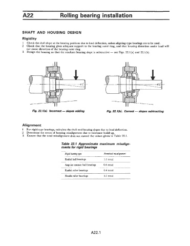
3 Design the housing so that the resultant bearing slope is subtractive - see Figs. 22.l(a) and 22.l(b).
Fig. 22.1 (a). Incorrect - slopes adding Fig. 22.l(b). Correct - slopes subtracting
Alignment
1 For rigid-type bearings, calculate the shaft and housing slopes due to load deflection.
2 Determine the errors of housing misalignment due to tolerance build-up.
3 Ensure that the total misalignment does not exceed the values given in Table 22.1.
Table 22.1 Approximate maximum misalign-
ments for rigid bearings
Rigid bearing type Permitted misalignment
Radial ball bearings 1 .O mrad
Angular contact ball bearings 0.4 mrad
Radial roller bearings 0.4 mrad
Needle roller bearings 0.1 mrad
A22.1