
Page 148 - The Tribology Handbook
P. 148
A26 Electromagnetic bearings
Electromagnetic bearings use powerful electromagnets to control the position of a steel shaft. Sensors are used to detect the
shaft position and their output is used to control the currents in the electromagnets in order to hold the shaft in a fixed
position. Steady and variable loads can be supported, and since no liquid lubricant is involved, new machine design
arrangements become possible.
RADIAL BEARING CONFIGURATION
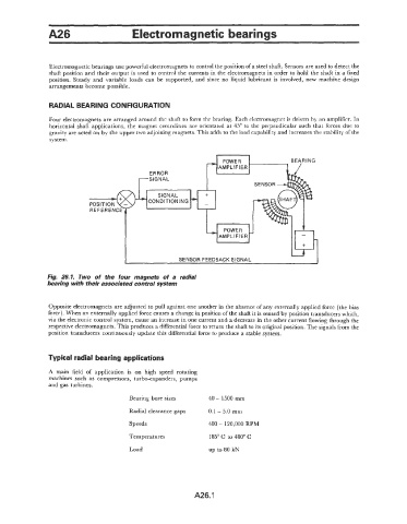
Four electromagnets are arranged around the shaft to form the bearing. Each electromagnet is driven by an amplifier. In
horizontal shaft applications, the magnet centrelines are orientated at 45" to the perpendicular such that forces due to
gravity are acted on by the upper two adjoining magnets. This adds to the load capability and increases the stability of the
system.
ERROR
-SIGNAL
tl
,P+ONDITIONING
"IUIYrnL
I ' L
REFERENCE
AMPLIFIER
I'
I SENSOR FEEDBACK SIGNAL I
Fig. 26.1. Two of the four magnets of a radial
bearing with their associated control system
Opposite electromagnets are adjusted to pull against one another in the absence of any externally applied force (the bias
force). When an externally applied force causes a change in position of the shaft it is sensed by position transducers which,
via the electronic control system, cause an increase in one current and a decrease in the other current flowing through the
respective electromagnets. This produces a differential force to return the shaft to its original position. The signals from the
position transducers continuously update this differential force to produce a stable system.
Typical radial bearing applications
A main field of application is on high speed rotating
machines such as compressors, turbo-expanders, pumps
and gas turbines.
Bearing bore sizes 40 - 1500 mm
Radial clearance gaps 0.1 - 5.0 mm
Speeds 400 - 120,000 RPM
Temperatures 185" C to 480" C
Load up to 80 kN
A26.1