
Page 184 - The Tribology Handbook
P. 184
Flexible couplings
400
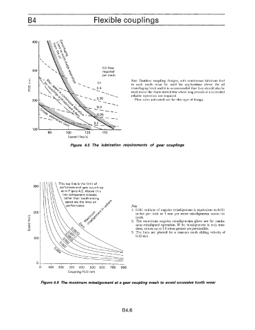
Oil flow
300 required
per mesh
E Note: Damless coupling designs, with continuous lubricant feed
E
n to each tooth must be used for applications above the oil
0 centrifuging limit and it is recommended that they should also be
n
used above the chain dotted line where long periods ofunattended
reliable operation are required.
200 Flow rates indicated are for this type of design.
100
80 100 120 140
Speed (Rev/s)
Figure 4.5 The lubrication requirements of gear couplings
This top line is the limit of
300 performance of gear couplings
as in Figure 4.2. Above this
line component stresses
rather than tooth sliding
Note
1. 0.001 radians of angular misalignment is equivalent to 0.001
20a inches per inch or 1 mm per metre misalignment across the
YI
\ mesh.
E 2. The maximum angular misalignments given are for contin-
% uous misaligned operation. If the misalignment is only tran-
Q sient, values up to 1.6 times greater are permissible.
v)
3. The lines are plotted for a constant tooth sliding velocity of
1 oc 0.12 mls
0
I I
100 200 300 400 500 600 700 800
Coupling PCD mm
Figure 4.6 The maximum misalignment at a gear coupling mesh to avoid excessive tooth wear
B4.6