
Page 183 - The Tribology Handbook
P. 183
Flexible couplings B4
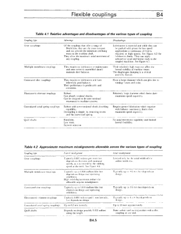
Table 4.1 Relative advantages and disadvantages of the various types of coupling
Coupling &,be Advantage Disadvantages
~ ~
Gear couplings Of the couplings that offer a range of Lubrication is essential and while they can
flexibilities, they are the most compact be packed with grease for low speed
and can provide the minimum overhung applications a continuous oil feed is
mass on the machine shaft. required at high speeds. See Figure 4.5 for
They allow the maximum axial movement of lubrication limits. They can apply
any coupling. substantial axial and lateral loads to the
coupled machines. See Figure 4.7.
Multiple membrane couplings They require no lubrication or maintenance Their relatively high mass can affect the
and once correctly assembled should lateral stability of machine rotors.
maintain their balance. The diaphragm clamping is a critical
assemhly feature.
Contoured disc couplings They require no lubrication and have Have a large diameter which ran give rise to
inherently good balance. windage losses and noise.
Their performance is predictable and
consis tent.
Elastomeric element couplings Robust. Relatively large diameter which limits their
Can absorb torsional shocks. maximum speed capability.
Can be designed to de-tune torsional
resonances in machine systems.
Convoluted axial spring couplings Robust with some torsional shock absorbing Require grease lubrication which together
capability. with balance consistency, limits their
Decoupling is simple, by removing covers maximum speed capability.
and the convoluted spring.
Quill shafts Simplicity. No axial movement capability and limited
Low mass. lateral flexibility.
Balance retention
Tabk 4.2 Approximate maximum misalignments allowable across the various types of coupling
Coupling ppe Lateral misalignment Axial misalignment
Gear couplings Typically 0.002 radians per mesh but Limited only by the axial width of the
depends on diameter and rotational widest tooth row.
speeds. as it is limited by the rubbing
speed at the teeth. See Figure 4.6.
~~
Multiple membrane couplings Typically up to 0.008 radianddisc but Typically up to 26 mm but depends on
depends on design and operating design.
conditions.
High axial displacements reduce the
allowable angular misalignment.
Contoured disc couplings Typically up to 0.010 radianddisc but Typically up to +6 mm but depends on
depends on design and operating design.
conditions.
Electromeric element couplings Typicaily 0.008 radians and I mm laterally, Typical!y up to 1 mm but depends on
but depends on design. design.
Convoluted axial spring couplings. Up to 0.2 mm laterally. Up to 10 mm approximately.
Quill shafts Depends on design possibly 0.002 radians None unless used in conjunction with a disc
along the length. coupling at one end.
B4.5