Page 185 - The Tribology Handbook
P. 185

Flexible couplings                                       B4


                 COUPLING EFFECTS
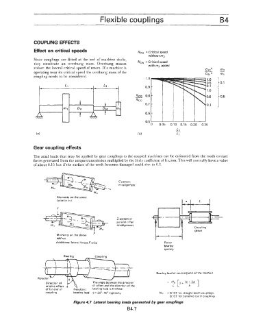
                  Effect on critical speeds                         N,,   = Critical speed
                                                                         without m2
                 Since couplings  are fitted  at the  end  of  machine  shafts,
                 they  constitute  an  overhung  mass.  Overhung  masses   Ncw = Critical speed
                                                                         withmz added
                 reduce the lateral critical speed of rotors. If a machine is
                 operating near its critical speed the overhung mass of the
                 coupling needs to be considered.                       1 .o
                                                                       0.5 -
                                                                       0.9
                                                                   -
                                                                       0.8
                                                                   Ncw
                                                                   Nc 0
                                                                       0.7


                                                                          0   0.05   0.10  0.15  0.20   0.25
                                                                                      -
                                                                                      L2
                                                                                      L1


                 Gear coupling effects
                 The axial Ioacls that may be applied by  gear couplings to the coupled  machines can be estimated from the tooth contact
                 forces generated from the torque transmission multiplied by the likely coefficient of friction. This will normally have a value
                 of about 0.15 but if the surface of the teeth becomes damaged could  rise  to 0.3.


                                                           C pattern
                                                           misalignment


                             Moments on the sleeve
                             balance out
                             F
                                                                                --
                                                          Z  pattern or
                                                          parallel offset
                                                          misalignment
                             Moments on rhe sleeve
                             add up.
                            Additional lateral forces F arise                    Rotor
                                                                                 bearing
                                                                                 spacing


                                                                             Bearing load at coupling end of the machine
                                                                                  =  - [*+  (L+2ai 1
                       Direction of           The angle between the direction       MR
                       relative offset        of offset and the direction of the     L      b
                       of far end of   ~~~~l~~~~ load is 8 where:
                                              bearing
                       coupling      bearing load  8 = 30"-45' typically      MR  = 0.16T for straight tooth couplings.
                                                                                   0.12T for barrelled tooth couplings.
                                     Figure 4.7  Lateral bearing loads generated by gear couplings
                                                               B4.7
   180   181   182   183   184   185   186   187   188   189   190