Page 245 - The Tribology Handbook
P. 245

B17                                  Piston rings


                6-30-12
                                 P


                5-25-10


                                                                                                        - 30
                4-20--8                                                                             20
                                     $-STANDARD  RADIAL  ,/
                                                                                                        - 25

                                                                                                     15
                                                                                                  *  -   - 20
                                                                                                   0
                                                                                                   X       N  C  .-
                                                                                                  -c       1
                                                                                                   N
                                                                                                     10   -15
                                                                                                   d       d
                                                                    P I for  tz. E,=  165.5 GN/mZ)
                                                                                                        - 10

                                                                                                        -5


                            100      200     300      400     500      600      700     800      900
                                                      RING  DIAMETER.  mm


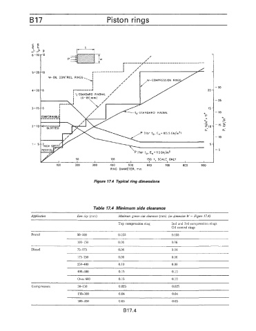
                                              Figure 17.4  Typical ring dimensions


                                              Table 17.4 Minimum side clearance

                Application           Bore sire  (mm)     Minimum groove side  clearance (mm) (on dimension W - Figure 17.4)
                                                          Top compression ring     2nd and 3rd compression rings
                                                                                   Oil control rings

                Petrol                50-100              0.035                    0.035
                                      100-150             0.06                     0.06
                                                                                 ~   ~~~         ~   ~~     ~
                Diesel                75-1 75             0.06                     0.04
                                      175-250             0.08                     0.06
                                      25woo               0.10                     0.08

                                      40C-600             0.15                     0.13
                                      Over 600            0.15                     0.13
                Compressors           50-150              0.025                    0.025
                                                                    ~~~   ~   ~~       ~            ~~
                                      150-300             0.04                     0.04
                                      30M50               0.05                     0 05
                                                            B17.4
   240   241   242   243   244   245   246   247   248   249   250