
Page 250 - The Tribology Handbook
P. 250
Cylinders and liners 918
Table 18.2 Cylinderk ylinder liner tolerances Nota:
Ovality Concentrin'ty 1. Choice of construction and material is dependent on
mm mm market being catered for: i.e. cost, power output or
delivery requirement, life requirement, size and in-
Monoblocs 0.025 FIM max tended application.
Press fit dry type cylinder 2. Choice of material is also dependent on material used
liners 0.150 FIM max 0.150 FIM max for pistons and rings and on any surface coatings given
Slip fit dry type cylinder to these. Also, but to a lesser extent, on the surface
liners* 0.050 FIM max 0.100 FIM max treatment.
Wet type cylinder liners* 0.025 FIM max 0.100 FIM max
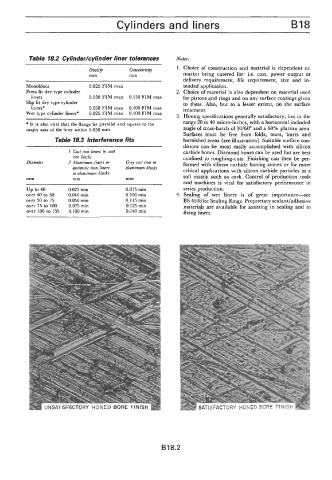
3. Honing specifications generally satisfactory; lies in the
* It is also vital that the flange be parallel and square to the range 20 to 40 micro-inches, with a horizontal included
major axis of the liner within 0.050 mm. angle of cross-hatch of 30/60" and a 60% plateau area.
Surfaces must be free from folds, tears, burrs and
Table 18.3 Interference fHs burnished areas (see illustration). Suitable surface con-
ditions can be most easily accomplished with silicon
I Cast iron lincrs in cast carbide hones. Diamond hones can be used but are best
iron blocks confined to roughing-cuts. Finishing can then be per-
Diameter 2 Aluminium liners or Grcy cast iron in formed with silicon carbide honing stones or for more
austenitic iron liners aluminium blocks critical applications with silicon carbide particles in a
in aluminium blocks
mm mm mm soft matrix such as cork. Control of production tools
and machines is vital for satisfactory performance in
up to 40 0.025 min 0.075 rnin series production.
over 40 to 50 0.040 min 0.100 min 4. Sealing of wet liners is of great importance-see
over 50 to 75 0.050 rnin 0.1 15 min BS 4518 for Sealing Rings. Proprietary sealant/adhesive
over 75 to 100 0.075 min 0.125 rnin materials are available for assisting in sealing and in
over 100 to 155 0.100min 0.140 min fixing liners.
B18.2