Page 252 - The Tribology Handbook
P. 252

Selection of seals                                      B19


                 BASIC SEAL TYPES AND THEIR CHARACTERISTICS
                 Dynamic seal

                 Sealing takes place between surfaces in sliding contact or narrowly separated.

                 Static seal1

                 Sealing takes place between surfaces which do not move relative  to each other.
                 Pseudo-static seal

                 Limited relative motion is possible at the sealing surfaces, or the seal itself allows limited motion; e.g. swivel couplings for
                 pipes, flexible diaphragms.

                 Exclusion seal

                 A device to restrict access of dirt, etc., to a system, often used in conjunction with a dynamic seal.
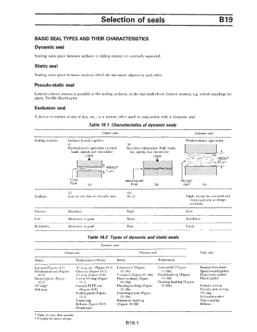
                                           Table 19.1  Characteristics of dynamic seals

                                                 Contact seals                                Clearance seals
                 Sealing interface   Surfaces loaded together:                           Predetermined separation
                                 (i)                         (ii)
                                 Hydrodynamic operation  (normal   Boundary lubrication  (high loads,
                                   loads, speeds and viscosities)   low speeds, low viscosities)
                                                                          LOAD


                                                                                       I
                                  FLUID                      MOLECULAR                 PRESET
                                  FILM                                                           b)
                                           (a)                 FILM        (b)          GAP
                                 6)                          (ii)
                 Leakage         Low to very low or virtually  zero   As  (i)            High, except for viscoseal and
                                                                                           centrifugal  seal at design
                                                                                           optimum
                            -
                 Friction        Moderate                    High                         Low

                 Life            Moderate to good            Short                        Indefinite
                                                                                                            ~~   ~~
                 Reliability     Moderate to good            Poor                        Good

                                          Table 19.2  Types of dynamic and static seals
                                                 Dynamic seals

                               Contact seals                       Clearance seals              Static seals
                 Rotary              RecipracatoT oscillatory   Rotary      Reciprocatory
                 Lip seal (Figure 19.1)   ‘U’ ring, etc. (Figure 19.4)  Labyrintht (Figure   Labyrinth7 (Figure   Bonded fibre sheet
                 Mechanical seal (Figure   Chevron (Figure 19.5)   19.10a)    19.10a)           Spiral wound gasket
                   19.2)             ‘0’ ring (Figure 19.6)   Viscoseal (Figure 19.10b)   Fixed bushing (Figure   Elastomeric gasket
                 Packed gland (Figure   Lobed ‘0’ ring (Figure   Fixed bushing (Figure   19.10d)   Piastic gasket
                   19.3)               19.7)              19.lOd)           Floating bushing (Figure
                 ‘0’ ring*           Coaxial PTFE seal   Floating bushing (Figure   19. l0e)    Sealant, setting
                 Felt ring            (Figure 19.8)       19.10e)                               Sealant, non-setting
                                     Packed gland (Figure   Centrifugal seal (Figure            ‘0’ ring
                                       19.3)              19.1Oc)                               Inflatable gasket
                                     Piston ring        Polymeric bushing                       Pipe coupling
                                     Bellows (Figure 19.9)   (Figure 19.101)                    Bellows
                                     Diaphragm
                 * Only for very slow speeds.
                 t Usually for steam or gas.
                                                             B19.1
   247   248   249   250   251   252   253   254   255   256   257