Page 264 - The Tribology Handbook
P. 264

Oil flinger rings and drain grooves                                    B21


                 Oil issuing from a bearing as end leakage will travel along   Where shafts must operate at any speed within a speed
                 a shaft for a  finite distance before  centrifugal dispersal of   range,  flingers  should  be  designed  by  the  foregoing  me-
                 the film takes place.  Many clearance seals will permit oil   thods using the minimum range speed.
                 leakage  fkom  the  bearing  housing  if  they  are  situated   Where shafts are further wetted by oil splash and where
                 within  the shaft oil-film  regime.  Flinger  rings  and drain   oil can drain down the inside walls of the bearing housing
                 grooves can prevent the oil reaching the seal.    on  to  the  thrower  itself,  larger  thrower  diameters  than
                                                                   given  by  equation  (1)  are  frequently  employed.  Figure
                                                                   2 1.2 gives a guide to ‘safe’ thrower proportions to meet this
                 GENERAL PROPORTIONS                               condition.
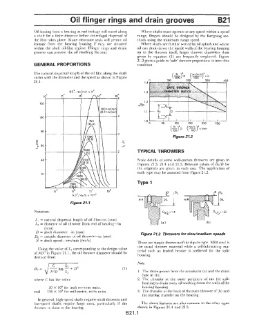
                 The natural dikpersal length ofthe oil film along the shaft
                 varies with the diameter and the speed as shown in Figure
                 21.1.                                                1.4  0     100      200      300      400

                                                                      1.3

                                                                      1.2
                                                                   210
                                                                      1.1
                                                          4           1.0 ‘    ,                             I
                                                                                                         I
                                                                                      1
                                                                                            150
                                                                         0     50    100   I I    200   250
                                                                                            rev/s
                                                                                           (751  rnm
                                                          3
                                                                                    Figure 21.2
                                                           .-
                                                            -
                                                            c
                                                            _I
                                                          2        TYPICAL THROWERS
                                                                   Scale details  of  some well-proven  throwers  are given  in
                                                                   Figures 21.3,  21.4 and 21.5.  Relevant values of  Do/D for
                                                                   the originals are given  in  each  case.  The application  of
                                                                   each type may be assessed from Figure 21.2.


                                                                                      0
                                   Figure 21.1

                 Notation:
                  L, = natural dispersal length  of oil film-in   (mm)
                  L, = distance of oil  thrower from end of bearing-in
                      (mm)
                  D = shaft diameter-in   (mm)                       Figure 21.3  Throwers for slow/medium speeds
                  Do = outside diameter of oil thrower-in   (mm)
                  N  = shaft speed--rev/min  (rev/s)               These are simple throwers of the slip-on type. Mild steel is
                                                                   the  usual  thrower  material  while  a  self-lubricating ma-
                   Using the value of L, corresponding to the design value
                 of ND3 in Figure 2 1.1,  the oil thrower diameter should be   terial  such  as  leaded  bronze  is  preferred  for  the  split
                                                                   housing.
                  derived from:
                                                                   Note:
                 Do =
                                                                   1.  The drain groove from the annulus in (a) and the drain
                                                                     hole in (b).
                 where  C has the value                            2.  The  chamfer  at  the  outer  periphery  of  the  (b)  split
                                                                     housing to drain away oil washing down the walls of the
                         30  X  IO6 for inch rev/min  units.         bearing housing.
                  and   136 X  IO6 for millimetre, rev/s units.    3.  The chamfer at the back of the main thrower of (b) and
                                                                     the mating chamfer on the housing.
                   In general, high-speed shafts require small throwers and
                 low-speed  shafts  require  large  ones,  particularly  if  the   The above features are also common to the other types
                  thrower is close to the bearing.                 shown in Figures 2 1.4 and 2 1.5.
                                                              B21.1
   259   260   261   262   263   264   265   266   267   268   269