
Page 265 - The Tribology Handbook
P. 265
B21 Oil flinger rings and drain grooves
= 1.2
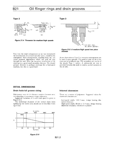
Figure 27.4 Throwers for mediumlhigh speeds
(TOP)
OIL DRAIN IBOTTOklI
Figure 21.5 A medium/high speed two piece
thrower
Note how the shaft enlargement on (a) has necessitated
the introduction of a second annular space, vented to the
atmosphere. Such enlargements, coupling hubs, etc. can As an alternative to Type 2, a two-piece arrangement can
create pressure depressions which can pull oil mist be used if space permits. The primary seal can be of the
through the seal. Note the two-piece construction of (b) visco seal or windback type. The secondary seal can be of
which gives a good sized secondary thrower. The shaped the simple Type 1 variety. A substantial air vent is
primary thrower is perhaps overlarge for a high-speed provided between the seals to combat partial vacuum on
machine, but this is a good fault! the air side.
DETAIL DIMENSIONS
Drain hole/oil groove sizing Internal clearances
Hole/groove area 2 k X thrower annular clearance area, These are a matter of judgement. Suggested values for
corresponding to maximum design tolerances. diametral clearance are:
Suggested variation of k with shaft speed is given in
Figure 2 l .6. Low-speed shafts: 1.25 X max. design bearing dia-
The individual diameter of the several drain holes metra1 clearance.
making up the above area should not be less than 5 mm High-speed shafts: D/250 or 2 X max. design bearing
in say. diametral clearance, whichever is greater.
N, rev/min
0 2000 4000 6000 8000
2
k
1
0 20 40 60 80 100 120
N, rev15
Figure 21.6
B21.2