
Page 377 - The Tribology Handbook
P. 377
Selection of oil pumps c21
Table 21. I System factors affecting choice of pump type
Factor WQJ in which pump choice is affected Remarks
~
Rate of flow Ttotai pump capacity = maximum equipment requirement+ known Actual selection may ex-
future increase in demand (if applicable) + 10 to 25% excess capacity ceed this because of
to cater for unexpected changes in system demand after long service standard pumps avail-
through wear in bearings, seals and pump able. Capacity of over
Determines pump size and contributes to determining the driving 200% may result foe
power small systems
Viscosity Lowest viscosity (highest expected operating temperature) is contributing
factor in determining pump size
Highest viscosity (lowest expected operating temperature) is contributing May influence decision
factor in determining driving power whether reservoir heat-
ing is necessary
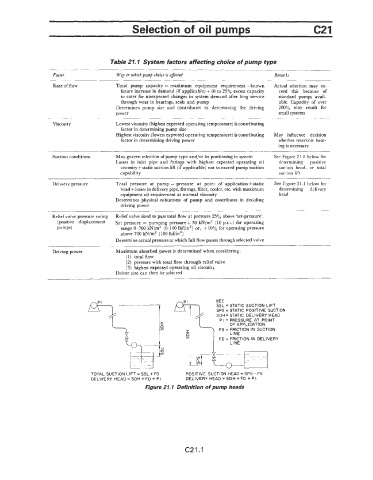
Suction conditions May govern selection of pump type and/or its positioning in system See Figure 21.1 below for
Losses in inlet pipe and fittings with highest expected operating oil determining positive
viscosity+static suction lift (if applicable) not to exceed pump suction suction head, or total
capability suction lift
Delivery pressure Total pressure at pump = pressure at point of applicationfstatic See Figure 21.1 below for
head+losses in delivery pipe, fittings, filter, cooler, etc. with maximum determining delivery
equipment oil requirement at normal viscosity head
Determines physical robustness of pump and contributes in deciding
driving power
Reliefvalve pressure eating Relief valve sized to pass total flow at pressure 25% above ‘set-pressure’.
(Positive displacement Set pressure = pumping pressure + 70 kN/m2 (10 p.s.i.) for operating
pumps) range 0-700 kN/mZ (0-100 Ibf/inz) or, + 10% for operating pressure
above 700 kN/m2 (100 Ibf/in2)
Determine actual pressure at which full flow passes through selected valve
Driving power Maximum absorbed power is determined when considering:
(1) total flow
(2) pressure with total flow through relief valve
(3) highest expected operating oil viscosity
Driver size can then be selected
KEY
SSL = STATIC SUCTION LIFT
SPS = STATIC POSITIVE SUCTION
SDH = STATIC DELIVERY HEAD
PI = PRESSURE AT POINT
OF APPLICATION
FS = FRICTION IN SUCTION
LINE
FD = FRICTION IN DELIVERY
LINE
TOTAL SUCTION LIFT = SSL + FS POSITIVE SUCTION HEAD = SPS - FS
DELIVERY HEAD = SDH + FD + PI DELIVERY HEAD = SDH + FD + PI
Figure 21. I Definition of pump heads
(221.1