
Page 375 - The Tribology Handbook
P. 375
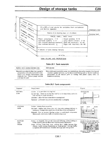
Design of storage tanks                                      c20


                                                                                                   Stationary  level

                                                                                                   Running  level

                                           Piston  compressors  1 - 8   Steam  turbines  5-10
                                           Hydraulic  systems  2-4     Large  electric  motors  5-10
                                           Gas  turbines  [land and  marine) 5  Steel  mill  machinery  20-60
                                           Gas  turbines (aircraft)  ’/2   Paper  mill  machinery  40-60


                                          = Volume  of  tank’s  internal  fitments

                                                                 w  to 3w                      =-

                                             TANK  VOLUME  AND  PROPORTIONS

                                                   Table 20. I  Tank materials

                  Stainless steel or dised aluminium all9   Mild steel plate
                  Material cost relatively high, but expensive   Most widely used material for tanks; low material cost, but surface requires cleaning and
                    preparation and surface protective treat-   treatment against corrosion, e.g.  by shot or sand blasting and (a) lanolin-based rust
                    ment is not needed.  Maintenance costs   preventative  (b)  oil  resistant  paint  (c)  coating  with  plastic  (epoxy  resin)  (d)
                    relatively  low.  Thinner gauge  stainless   aluminium spraying
                    steel may be used
                                                                                                 ~~

                                                  Table 20.2  Tank components

                  Component        Design Jecrtures                                     Diagram
                   RETURN          Locatton.  at or just above running level             PERFORATED
                   LINE            &e  and slope:  chosen to run less than half full to let foam drain, and with
                                    least velocity to avoid turbulence
                                   Altemuh : allow full bore return below running level
                                   Rcjincmmt:  perforated tray prevents aeration due to plunging


                    SUCTION        Location:  remote from return line                    PfVOT   STCP   FLOAT
                    LINE           Inlet dcptlr : shallow inlet  draws clean oil ; deep inlet prolongs delivery in
                                    emergency. Compromise usually two-thirds down from running level
                                   Rejnmcnt:  filter or strainer;  floating suction  to avoid depth  compromise
                                    (illustrated)  ; anti-vortex baffle to avoid drawing in air


                    BAFFLES        Purpose:  see diagram. Also provide structural stiffening, inhibit sloshing in   0 WEIR  TO  LOCALISE  TURBULENCE
                   AND              mobile systems, prevent direct Row between return and suction   @:
                    WEIRS          Design:  Settling  needs  long,  slow,  uniform  flow;  baffles  increase  flow
                                    velocity. Avoid causing constrictions or ‘dead pockets’.  Arrange baffles
                                    to separate off cleanest layer. Consider drainage and venting needs
                                                                                         0 BAFFLE  TO  TRAP  SINKING
                                                                                           CONTAMINANTS
                                                             c20.1