Page 370 - The Tribology Handbook
P. 370

C18                           C i rcu I at i o n systems


                          MAIN  DELIVERY                                    MAIN  DELIVERY
                             J.
                                     4 in BORE  -1 x  FLOW

                                     hi” BORE  =3xFLOW
                                                                              (c
                                      3/8 in BORE : x  FLOW                          %in  BORE -16xFLOW
                                              14
                                                                              ir


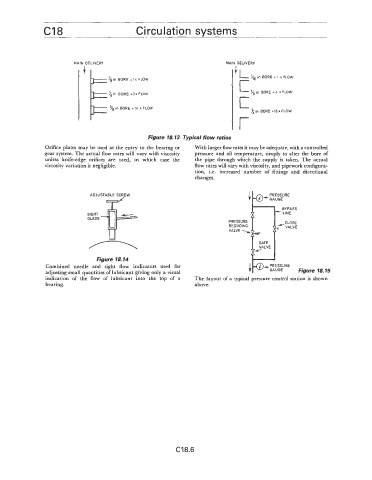
                                                  Figure 18.13  Typical flow ratios
                Orifice plates may be used  at the entry to the bearing or   With larger flow rates it may be adequate, with a controlled
                gear system. The actual flow rates will vary with viscosity   pressure  and oil  temperature, simply to alter the bore of
                unless  knife-edge  orifices  are  used,  in  which  case  the   the  pipe  through  which  the supply  is  taken.  The actual
                viscosity variation is negligible.                flow rates will vary with viscosity, and pipework configura-
                                                                  tion,  i.e.  increased  number  of  fittings  and  directional
                                                                  changes  .
                                                                                       +
                               ADJUSTABLE  SCREW                                    ‘8” *GAUGE PRF:3EE

                                                                                               BYPASS
                              SIGHT
                              GLASS
                                                                             PRESSURE
                                                                                     u
                                                                             REDUCING

                                                                                       VALVE
                                 Figure 18.14
                Combined  needle  and  sight  flow  indicators  used  for
                adjusting small quantities of lubricant giving only a visual
                indication  of  the  flow  of  lubricant  into  the  top  of  a   The layout of  a  typical pressure control station  is  shown
                bearing.                                          above.


                                                            C18.6
   365   366   367   368   369   370   371   372   373   374   375