
Page 369 - The Tribology Handbook
P. 369
C i rcu I at i o n svste m s 618
Table 18.1 Main components of group 2 systems
Storage tank One or more storage tanks, dependent on water contamination, will be required with a capacity of between
20 and 40 times the throughput per minute of the system
Tank heating Electric, steam or hot-water heating are used for raising the temperature of the lubricant in the storage tank
Pumps One or more main pumps and a stand-by pump are required. The main pumps should have a capacity of at
least 2506 in excess of basic system requirement
-__
~~
Pressure conlrol oalue System pressure will be maintained by the use of pressure control valves
.Von-return ualues A non-return valve is required after each pump unit
___
Se(f-cltaning strainer Either manual or automatic, single or duplex self-cleanIf:g strainers will be used for cleaning the oil
Magndzc stratner Particularly in the case ofgear lubrication, magnetic strainers may be fitted whether in the supply line and/or
on the return oil connection to the tank
P~tr:ure vessel Pressure vessels may be required in order to maintain a flow of oil in the event of a power failure, to allow the
run-down of machinery or the completion of a machine aperation
~~~ ~~
Cooler A cooler may be used to extract the heat taken away from the equipment to the lubricant and maintain the
viscosity in the system prior to the supply to the lubrication points
~
Pressure-reducing stations On extensive systems the lubrication points can be split into groups for controlling the flow rate by means
of a pressure-reducing station, followed by either orifice plates or simple pipe sizing flow control
Waterlsludge trap Where water contamination is likely a water/sludge trap should be fitted in the return line immediately before
the tank
Valuing All major equipment should be capable of being shut off by the use of gate valves for maintenance purposes
In the case of filters and coolers a bypass arrangement is necessary
Instrumentation Normal instrumentation will cater for the specific system requirements, including pressure gauges,
thermometers, thermostats, pressure switches, recording devices, etc.
CONTROL OF LUBRICANT QUANTITIES
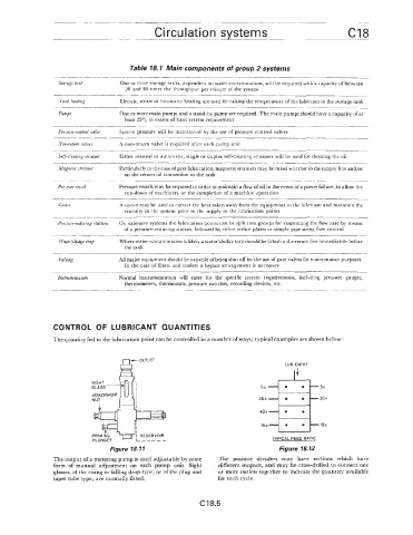
The quantity fed to the lubrication point can be controlled in a number ofways; typical examples are shown below:
LUB. ENTRY
EOUTLET
5x 5x
20x 20 x
I/ 15x 15x
I RESERVOIR
I------ TYPICAL FEED RATIO
Figure lip. 11 Figure 18.12
The output ofa metering pump is itself adjustable by some The positive dividers may have sections which have
form of manual adjustment on each pump unit. Sight different outputs, and may be cross-drilled to connect one
glasses, of the rising or falling drop type, or of the plug and or more outlets together to increase the quantity available
taper tube type, are normally fitted. for each cycle.
C18.5