
Page 371 - The Tribology Handbook
P. 371
Commissioning lubrication systems c19
TOTAL-LOSS SYSTEMS PUMP
L ERING VALVES
CHANGEOVER
VALVE
YPE
VALVE
(DIRECT SUPPLY
FEED) LINES
SECONDARY
DELIVERY
LINES APPLICATION
TO POINTS OF TO POINTSOF SECONDARY DELIVERY
APPLICATION APPLICATION LINES
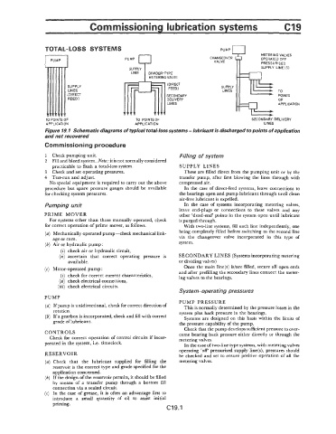
Figure 19. I Schematic diagrams of typical total-loss systems - lubricant is discharged to points of application
and not recalvered
Commissioning procedure
1 Check pumping unit. Filling of system
2 Fill and bleed system. Note: it is not normally considered
practicable to flush a total-loss system. SUPPLY LINES
3 Check andset operating pressures. These are filled direct from the pumping unit or by the
4 Test-run and adjust. transfer pump, after first blowing the lines through with
No special equipment is required to carry out the above compressed air.
procedure but spare pressure gauges should be available In the case of direct-feed systems, leave connections to
for checking system pressures. the bearings open and pump lubricant through until clean
air-free lubricant is expelled.
Pumping unit In the case of systems incorporating metering valves,
leave end-plugs or connections to these valves and any
PRIME MOVER other ‘dead-end’ points in the system open until lubricant
For systems other than those manually operated, check is purged through.
for correct operation of prime moves, as follows. With two-line systems, fill each line independently, one
(a) Mechanically operated pump-check mechanical link- being completely filled before switching to the second line
age or cam. via the changeover valve incorporated in this type of
(6) Air or hydraulic pump : system.
(i) check air or hydraulic circuit,
(ii) ascertain that correct operating pressure is SECONDARY LINES (Systems incorporating metering
available. or dividing valves)
Once the main line(s) islare filled, secure all open ends
(c) Motor-operated pump: and after prefilling the secondary lines connect the meter-
(i) check for correct current characteristics, ing valves to the bearings.
(ii) check electrical connections,
(iii) check electrical circuits.
System-operating pressures
PUMP
PUMP PRESSURE
(a) If pump is unidirectional, check for correct direction of This is normally determined by the pressure losses in the
rotation. system plus back pressure in the bearings.
(b) If a gearbox is incorporated, check and fill with correct Systems are designed on this basis within the limits of
grade of lubricant. the pressure capability of the pump.
Check that the pump develops sufficient pressure to over-
CONTROLS come bearing back pressure either directly or t
Check for correct operation of control circuits if incor- metering valves.
porated in the system, i.e. timeclock. In the case of two-line type systems, with metering valves
operating ‘off pressurised supply line(s), pressures should
RES ERVO I I;I be checked and set to ensure positive operation of all the
(a) Check that the lubricant supplied for filling the metering valves.
reservoir is the correct type and grade specified for the
application concerned.
(6) If the design of the reservoir permits, it should be filled
by means of a transfer pump through a bottom fill
connection via a sealed circuit.
(c) In the case of grease, it is often an advantage first to
introduce a small quantity of oil to assist initial
priming.
(219.1