
Page 372 - The Tribology Handbook
P. 372
c19 Commissioning lubrication systems
Running tests and adjustments
SYSTEM OPERATION CONTROLS
Operate system until lubricant is seen to be discharging Where adjustable electrical controls are incorporated,
at all bearings. If systems incorporate metering valves, each e.g. timeclock, these should be set as specified.
valve should be individually inspected for correct operation.
ALARM
ADJUSTMENT Electrical or mechanical alarms should be tested by
In the case of direct-feed systems, adjust as necessary the simulating system faults and checking that the appropriate
discharge(s) from the pump and, in the case of systems alarm functions. Set alarms as specified.
operating from a pressure line, adjust the discharge from
the metering valves.
Fault finding
RELIEF OR BYPASS VALVE
Check that relief or bypass valve holds at normal system- Action recommended in the event of trouble is best deter-
operating pressure and that it will open at the specified mined by reference to a simple fault finding chart as
relief pressure. illustrated in Table 19.2.
CIRCULATION SYSTEMS
--
Corn miss ion i ng procedure TO
1
:!INTS
1 Flush system. Note: circulation systems must be R~~uR* -/
APPLICATION
thoroughly flushed through to remove foreign solids. Ir-‘
2 Check main items of equipment. TANK(S1
..--111111
3 Test-run and adjust. PUMP(S) INTERMEDIATE EQUIPMENT
No special equipment is required to carry out the above
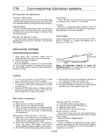
but spare pressure gauges for checking system pressures, Figure 19.2 Schematic diagram of typical oil-
etc., and flexible hoses for bypassing items of equipment, circulation system. Oil is discharged to points of appli-
should be available. cation, returned and re-circulated
Flushing
1 Use the same type of oil as for the final fill or flushing 4 During flushing, tap pipes and flanges and alternate oil
oil as recommended by the lubricant supplier. on an eight-hour heating and cooling cycle.
2 Before commencing flushing, bypass or isolate bearings 5 After flushing drain oil, clean reservoir, filters, etc.
or equipment which could be damaged by loosened 6 Re-connect bearings and equipment previously isolated
abrasive matter. and refill system with running charge of oil.
3 Heat oil to 60-70°C and continue to circulate until the
minimum specified design pressure drop across the
filter is achieved over an eight-hour period.
Main items of equipment
RESERVOIR MOTOR-DRIVEN PUMP(S)
(a) Check reservoir is at least two-thirds full. (a) Where fitted, check coupling alignment.
(b) Check oil is the type and grade specified. (b) Check for correct current characteristics.
(c) Where heating is incorporated, set temperature-regu- (c) Check electrical circuits.
lating instruments as specified and bring heating into (d) Check for correct direction of rotation.
operation at least four hours prior to commencement PUMP RELIEF VALVE
of commissioning.
Note setting of pump relief valve, then release spring to
its fullest extent, run pump motor in short bursts and check
ISOLATING AND CONTROL VALVES system for leaks.
Where fitted, the following valves must initially be left Reset relief valve to original position.
open: main suction; pump(s) isolation; filter isolation;
cooler isolation ; pressure-regulator bypass. CENTRIFUGE
Where fitted, the following valves must initially be Where a centrifuge is incoporated in the system, this is
closed : low suction; filter bypass; cooler bypass ; normally commissioned by the manufacturer’s engineer,
pressure-regulator isolation ; pressure-vessel isolation. but it should be checked that it is set for ‘clarification’ or
For initial test ofitems of equipment, isolate as required. ‘purification’ as specified.
c19.2