Page 367 - The Tribology Handbook
P. 367

Ci rcu I at i o n systems                                C18


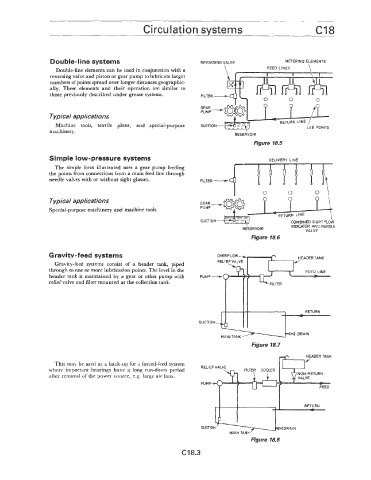
                  Double-line systems                                                           METERING ELEMENTS
                    Double-line elements can be used in conjunction with a
                  reversing valve and piston or gear pump to lubricate larger
                  numbers of points spread over longer distances geographic-
                  ally.  These  elements  and  their  operation  are  similar  to   FILTER -
                  those previously described under grease systems.


                  Typical applications
                   Machine  itools,  textile  plant,  and  special-purpose
                 machinery.
                                                                               RESERVOIR
                                                                                     Figure 18.5

                 Simple low-pressure systems                                              DELIVERY  LINE
                   The simple form illustrated  uses  a  gear pump  feeding
                 the points from connections from a main feed line through
                 needle valves with or without sight glasses.


                  Typical applications
                 Special-purpose machinery and machine tools.
                                                                                                 COMBINED SIGHT FLOW
                                                                                                  INDICATOR AND NEEDLE
                                                                                 RESERVOIR
                                                                                                      VALVE
                                                                                    Figure 18.6

                 Gravity-feed systems
                   Gravity-feed  systems consist  of  a  header  tank,  piped
                 through to one or more lubrication points. The level in the
                 header tank  is maintained by a  gear or other pump with
                 relief valve and filter mounted at the collection tank.


                                                                                    Figure 18.7
                                                                                                      YER
                   This may be used as a back-up for a forced-feed system                                   TANK
                 where  important bearings have  a long  run-down  period   RELIEF’ tALVE   f3LTEY
                                                                           ~n,  COYLER
                 after removal of the power source, e.g. large air fans.                             .  :TURN
                                                                    PUM


                                                                                                      RETURN


                                                                    SUCTION                    DRAIN
                                                                             MAIN TANK
                                                                                    Figure 18.8

                                                             C18.3
   362   363   364   365   366   367   368   369   370   371   372