
Page 363 - The Tribology Handbook
P. 363
Mist svstems C17
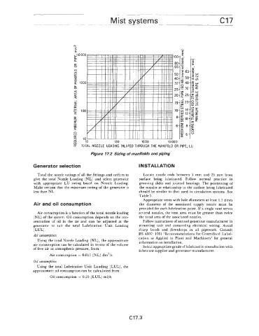
Figure 17.2 Sizing of manifolds and piping
Generator selection INSTALLATION
Total the nozzle ratings of all the fittings and orifices to Locate nozzle ends between 3 mm and 25 mm from
give the total Nozzle Loading (NL) and select generator surface being lubricated. Follow normal practice in
with appropriate LU rating based on Nozzle Loading. grooving slides and journal bearings. The positioning of
Make certain that the minimum rating of the generator is the nozzles in relationship to the surface being lubricated
less than NL. should be similar to that used in circulation systems. See
Table 5.
Appropriate vents with hole diameters at least 1.5 times
Air and oil consumption the diameter of the associated supply nozzle must be
provided for each lubrication point. If a single vent serves
Air consumption is a function of the total nozzle loading several nozzles, the vent area must be greater than twice
(NL) of the system. Oil consumption depends on the con- the total area of the associated nozzles.
centration of oil in the air and can be adjusted at the Follow instructions of aerosol generator manufacturer in
generator to suit the total Lubrication Unit Loading mounting unit and connecting electrical wiring. Avoid
(LUL) . sharp bends and downloops in all pipework. Consult
Air consumption BS 4807: 1991 ‘Recommendations for Centraiised Lubri-
Using the total Nozzle Loading (NL), the approximate cation as Applied to Plant and Machinery’ for general
air consumptia’n can be calculated in terms of the volume information on installation.
Select appropriate grade of lubricant in consultation with
of free air at atmospheric pressure, from :
lubricant supplier and generator manufacturer.
Air consumption = 0.015 (NL) dm3/s
Oil consumption
Using the total Lubrication Unit Loading (LUL), the
approximate oil consumption ca.n be calculated from :
Oil consumption = 0.25 (LUL) ml/h
C17.3