
Page 361 - The Tribology Handbook
P. 361
Mist systems C17
Mist systems, generically known as aerosol systems, em- Table 17.1 Load factors
ploy a generator supplied with filtered compressed air from
the normal shop air main, to produce a mist offinely divided
oil particles having little tendency to wet a surface. The Wjbd values
actual air pressure applied to the inlet of the generator is
controlled and adjusted to provide the desired oil output.
The mist must be transmitted at a low velocity below -a x
6 m/s and a Iow pressure usually between 25 and 50 mbar -.= h x
gauge through steel, copper or plastic tubes. The tubes <
must be smooth and scrupulously clean internally. A
At the lubrication point the mist is throttled to atmos-
pheric pressure through a special nozzle whose orifice size Type of bearing Load factor F
controls the total amount of lubricant applied and raises
the mist velocity to a figure in excess of40 mjs. This causes Ball 1 2 Y)
the lubricant to wet the rubbing surfaces and the air is Hollow roller 3
permitted to escape to atmosphere. Empirical formulae Needle roller 1
using an arbitrary unit-the ‘Lubrication Unit’, are used
to assess the lubricant requirements of the machine, the Straight roller 1
total compressed air supply required and the size of tubing Spherical roller 2
needed.
Taper roller 1
Plainjournal (see Notes) 1 2 4 8
ESlG N
W
Notes: for explanation- see Table 17.2. For plain journal bearings
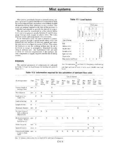
The essential parameters of‘ components are indicated bd
in Table 17.2 .and the load factors for bearings are given in with high end losses or made of white metal, double these load
Table 17.1. factors.
Table 17.2 Information required for the calculation of lubricant flow rates
Type of component
Foimv- Ball Plain Cam In-
Essentia1paramer:ers units and ~~~l (jour- G~~~ Worm G~~~ Rack and Mou- Roller uerted Con-
.yym- roller nuts rial) pair and train and +l- ing $:: tooth veyor
bois bearing bearing gear pinion lower slide chain chain
Contact length of mm b X X
bearing surface
Shaft diameter mm d X X
Load factor (see F x X
Table 17.1)
Loadon bearing N W X
Length of chain m l X
Maximum diameter mrn D X
____
Number of rowj of N X X x
balls or rollers or
chain strands
Pitch circle diameters mm P X x x x x x x x
-Gears-Worm-
Sprocket or clut
Chain link pitch mm C X
Speed of rotatiom revjs n x x
Contact width ofslide mm w x x x x x x x x
or gear or chain
width
Note: ‘X’ denotes information that is required for each type of component
C17.1