
Page 362 - The Tribology Handbook
P. 362
C17 Mist svstems
The Lubrication Unit (LU) rating of each component Nozzle sizes
should be calculated from the formulae in Table 17.3,
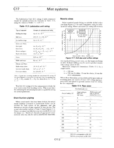
using the values in Tables 17.1 and 17.2. Select standard nozzle fitting or suitable drilled orifice
size from Figure 17.1 for each component using its calcu-
Table 17.3 Lubrication unit rating lated LU rating. Where calculated LU rating falls between
Type of component Formulae for lubrication unit rating
Rolling bearings 4(d.F.4. IO-'
Ball nuts 4P[(N-1)+10].
Journal bearings 2(b.d.F). lo4
Gears (see Note)
Gear pair
Gear train
Worm and gear
Rack and pinion "0 1.0 2.0 3.0"
EQUIVALENT DRILL SIZES, mm
Cams 2(D.w).104 Figure 17.1 Brill size and orifice ratings
Slides and ways 8(b.m). lo-' two standard fitting or drill sizes, use the larger size fitting
or drill. Multiple drillings may be used to produce nozzles
Chains (see Note) with ratings above 20 LU.
Roller chain drive (N.P.c) (n)+. Maximum component dimensions (Table 17.1) for a
Inverted tooth chain 5(P.w) (n)*. IO-' single nozzle.
Conveyor chains 5w (25i+~). 10-4 b = 150mm
w = 150 mm for slides, 12 mrn for chains, 50 mm for
Notes: if gears are reversing double the calculated LU rating. If other components.
the pitch diameter of any gear exceeds twice that of a mating gear, Where these dimensions are exceeded and for gear trains or
i.e. P, > 2P2, consider PI = 2P2. For chain drives if n < 3 use reversing gears use nozzles of lower LU rating appropri-
n = 3. ately sized and spaced to provide correct total LU rating
for the component.
Total the LU ratings of all the components to obtain the Table 17.4 Pipe sizes
total Lubrication Unit Loading (LUL). This is used later Distribution pipe size
for estimating the oil consumption and as a guide for setting
the aerosol generators. copper tubing to Medium series steel
Nozzle loading, LU ISO 274 pipe to IS0 65,
OD (mm) nominal bore (mm)
Distribution piping 10 6 -
When actual nozzle sizes have been decided, the actual 15 8 6
nozzle loadings (measured in Lubrication Units) can be
totalled for each section of the pipework, and this 30 10 8
determines the size of pipe required for that section. The 50 12 10
actual relationship is given in Table 17.4 and Figures 17.2.
Where calculated size falls between two standard sizes use 75 16 -
the larger size. Machined channels of appropriate cross-
sectional area may also be used as distribution manifolds. 100 20 15
200 25 20
300 32 25
500 40 32
650 50 40
1000 63 50
IS0 274 corresponds to BS 2871
IS0 65 corresponds to BS 1387
c17.2