
Page 234 - The Unofficial Guide to Lego Mindstorms Robots
P. 234
223
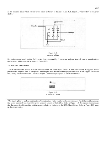
so that it doesn't matter which way the active sensor is attached to the input on the RCX. Figure 11-5 shows how to set up the
diodes.∗
Figure 11-5.
A signal splitter
Remember, power is only applied for 3 ms at a time, punctuated by .1 ms sensor readings. You will need to smooth out the
power supply with a capacitor, as shown in Figure 11-5.
The Touchless Touch Sensor
This section describes how to build an interface circuit for a Hall effect sensor. A Hall effect sensor is triggered by the
presence of a magnetic field. If you place a small magnet near the sensor in the proper orientation, it will trigger. The sensor
itself is very small and looks like a transistor. Figure 11-6 shows a photograph of a Hall effect sensor.
Figure 11-6.
A Hall effect sensor
∗The signal splitter is really a combination of two circuits, a bridge rectifier and a current router. The bridge rectifier ensures
that power is correctly supplied to the active sensor; it consists of the left four diodes in Figure 11-5. The current router ensures
that the sensor signal is supplied with the correct polarity to the input on the RCX. The right two diodes in Figure 11-5 make
up the current router.