
Page 233 - The Unofficial Guide to Lego Mindstorms Robots
P. 233
222
Active Sensor Magic
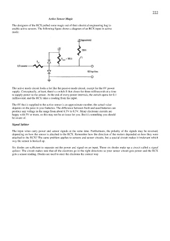
The designers of the RCX pulled some magic out of their electrical engineering bag to
enable active sensors. The following figure shows a diagram of an RCX input in active
mode:
The active mode circuit looks a lot like the passive mode circuit, except for the 8V power
supply. Conceptually, at least, there's a switch S that closes for three milliseconds at a time
to supply power to the sensor. At the end of every power intervals, the switch opens for 0.1
millisecond, and the RCX takes a reading from the input.
The 8V that is supplied to the active sensor is an approximate number; the actual value
depends on the juice in your batteries. The difference between fresh and used batteries can
produce any voltage in the range from about 6.5V to 8.5V. Many electronic circuits are
happy with 5V or more, so this may not be an issue for you. But it's something you should
be aware of.
Signal Splitter
The input wires carry power and sensor signals at the same time. Furthermore, the polarity of the signals may be reversed,
depending on how the sensor is attached to the RCX. Remember how the direction of the motors depended on how they were
attached to the RCX? The same problem applies to sensors and sensor circuits, but a special circuit makes it irrelevant which
way the sensor is hooked up.
Six diodes are sufficient to separate out the power and signal on an input. These six diodes make up a circuit called a signal
splitter. The circuit makes sure that all the electrons go in the right directions so your sensor circuit gets power and the RCX
gets a sensor reading. Diodes are used to steer the electrons the correct way