
Page 235 - The Unofficial Guide to Lego Mindstorms Robots
P. 235
224
Not all Hall effect sensors are created equal. Some have on-board circuitry that processes the sensor's signal and converts it to
a boolean electrical signal. Some respond to one polarity of magnetic field; some respond to both. Read the fine print closely
when you buy a Hall effect sensor.
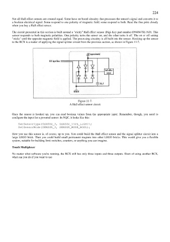
The circuit presented in this section is built around a "sticky" Hall effect sensor (Digi-Key part number DN6847SE-ND). This
sensor responds to both magnetic polarities. One polarity turns the sensor on, and the other turns it off. The on or off setting
"sticks" until the opposite magnetic field is applied. The processing circuitry is all built into the sensor. Hooking up the sensor
to the RCX is a matter of applying the signal splitter circuit from the previous section, as shown in Figure 11-7.
Figure 11-7.
A Hall effect sensor circuit
Once the sensor is hooked up, you can read boolean values from the appropriate input. Remember, though, you need to
configure the input for a powered sensor. In NQC, it looks like this:
SetSensorType(SENSOR_3, SENSOR_TYPE_LIGHT);
SetSensorMode(SENSOR_3, SENSOR_MODE_BOOL);
How you use this sensor is, of course, up to you. You could build the Hall effect sensor and the signal splitter circuit into a
large LEGO brick. Then you could build small permanent magnets into other LEGO bricks. This would give you a flexible
system, suitable for building limit switches, counters, or anything you can imagine.
Touch Multiplexer
No matter what software you're running, the RCX still has only three inputs and three outputs. Short of using another RCX,
what can you do if you want to use