
Page 125 - Welding of Aluminium and its Alloys
P. 125
110 The welding of aluminium and its alloys
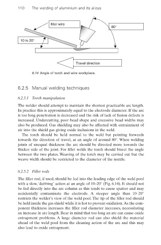
filler wire
80°
10 to 20°
Travel direction
6.14 Angle of torch and wire workpiece.
6.2.5 Manual welding techniques
6.2.5.1 Torch manipulation
The welder should attempt to maintain the shortest practicable arc length.
In practice this is approximately equal to the electrode diameter. If the arc
is too long penetration is decreased and the risk of lack of fusion defects is
increased. Undercutting, poor bead shape and excessive bead widths may
also be produced. Gas shielding may also be affected with entrainment of
air into the shield gas giving oxide inclusions in the weld.
The torch should be held normal to the weld but pointing forwards
towards the direction of travel, at an angle of around 80°. When welding
joints of unequal thickness the arc should be directed more towards the
thicker side of the joint. For fillet welds the torch should bisect the angle
between the two plates. Weaving of the torch may be carried out but the
weave width should be restricted to the diameter of the nozzle.
6.2.5.2 Filler rods
The filler rod, if used, should be fed into the leading edge of the weld pool
with a slow, ‘dabbing’ action at an angle of 10–20° (Fig. 6.14). It should not
be fed directly into the arc column as this tends to cause spatter and may
accidentally contaminate the electrode. A steeper angle than 10–20°
restricts the welder’s view of the weld pool. The tip of the filler rod should
be held inside the gas shield while it is hot to prevent oxidation.As the com-
ponent thickness increases the filler rod diameter increases, necessitating
an increase in arc length. Bear in mind that too long an arc can cause oxide
entrapment problems. A large diameter rod can also shield the material
ahead of the weld pool from the cleaning action of the arc and this may
also lead to oxide entrapment.