
Page 124 - Welding of Aluminium and its Alloys
P. 124
TIG welding 109
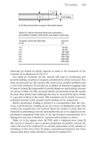
2D
D 0.4D radius
6.13 Recommended tungsten electrode shape.
Table 6.4 Recommended electrode diameters –
zirconiated tungsten electrodes and argon shield gas
Tungsten electrode diameter Current
(mm) (A)
1.0 20–50
1.6 50–80
2.4 80–160
3.2 160–225
4.0 225–330
5.0 330–400
6.4 400–550
electrode tip should be lightly tapered to assist in the formation of the
rounded tip as illustrated in Fig. 6.13.
Too small an electrode for the current will lead to overheating and
possibly melting, resulting in tungsten contamination of the weld pool. Too
large an electrode for the current will result in arc stability problems and
a very wide weld pool. Electrodes are available in diameters ranging from
0.3mm to 6.4mm. Recommended electrode diameters and welding currents
are given in Table 6.4. The electrode should not protrude from the nozzle
by more than about 6mm, although this may be extended by up to 10mm
if a gas lens is fitted to the torch. This extension can be useful if access is
restricted because of the ceramic nozzle fouling on the component.
Before production welding is started it is recommended that the elec-
trode is preheated by forming an arc on a piece of aluminium scrap. This
enables the rounded tip to be formed, allows the welder to check that the
electrode is performing correctly and enables the arc to be reignited on the
production component with ease. If the tip becomes contaminated or is
damaged in any way it should be reground and reformed as above.
Table 6.4 is for square wave AC-TIG with a balanced wave form. If
the current is biased to give a greater proportion of positive current the
value will need to be reduced by an amount appropriate to the amount of
imbalance in the wave form. If using a conventional balanced sine wave
current then these values should be reduced by around 25%.