
Page 128 - Welding of Aluminium and its Alloys
P. 128
TIG welding 113
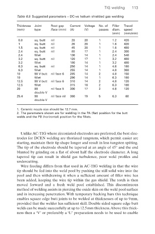
Table 6.5 Suggested parameters – DC-ve helium shielded gas welding
Thickness Joint Root gap Current Voltage No. of Filler Travel
(mm) type /face (mm) (A) (V) passes diam. speed
(mm) (mm/min)
0.8 sq. butt nil 20 20 1 1.2 420
1 sq. butt nil 26 20 1 1.6 420
1.5 sq. butt nil 45 20 1 1.6 480
2.4 sq. butt nil 80 17 1 2.4 300
2.4 fillet 130 14 1 2.4 540
3.2 sq. butt nil 120 17 1 3.2 480
3.2 fillet 180 14 1 3.2 480
6.3 sq. butt nil 250 14 1 4.8 180
6.3 fillet 255 14 1 4.8 360
10 90 V-butt nil face 6 285 14 2 4.8 150
10 fillet 290 14 1 6.3 180
12.5 90 V-butt nil face 6 310 14 2 4.8 120
12.5 fillet 315 16 2 6.3 180
20 90 nil face 5 300 17 2 4.8 120
double-V
25.4 90 nil face nil 360 19 5 6.3 60
double-V
1. Ceramic nozzle size should be 12.7 mm.
2. The parameters shown are for welding in the PA (flat) position for the butt
welds and the PB (horizontal) position for the fillets.
Unlike AC-TIG where zirconiated electrodes are preferred, the best elec-
trodes for DCEN welding are thoriated tungstens, which permit easier arc
starting, maintain their tip shape longer and result in less tungsten spitting.
The tip of the electrode should be tapered at an angle of 45° and the end
blunted by grinding on a flat of about half the electrode diameter. A long
tapered tip can result in shield gas turbulence, poor weld profiles and
undercutting.
Wire feeding differs from that used in AC-TIG welding in that the wire
tip should be fed into the weld pool by pushing the still solid wire into the
pool and then withdrawing it when a sufficient amount of filler wire has
been added, keeping the wire tip within the gas shield. The torch is then
moved forward and a fresh weld pool established. This discontinuous
method of welding assists in piercing the oxide skin on the weld pool surface
and in increasing penetration. With temporary backing bars this technique
enables square edge butt joints to be welded at thicknesses of up to 9mm,
provided that the welder has sufficient skill. Double sided square edge butt
welds can be made successfully at up to 12.5mm thickness.Above this thick-
ness then a ‘V’ or preferably a ‘U’ preparation needs to be used to enable