
Page 162 - Welding of Aluminium and its Alloys
P. 162
MIG welding 145
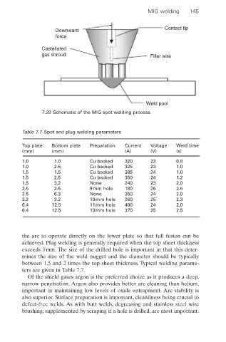
Contact tip
Downward
force
Castellated
gas shroud Filler wire
Weld pool
7.20 Schematic of the MIG spot welding process.
Table 7.7 Spot and plug welding parameters
Top plate Bottom plate Preparation Current Voltage Weld time
(mm) (mm) (A) (V) (s)
1.0 1.0 Cu backed 320 23 0.8
1.0 2.5 Cu backed 325 23 1.0
1.5 1.5 Cu backed 335 24 1.0
1.5 2.5 Cu backed 350 24 1.2
1.5 3.2 None 240 23 2.0
2.5 2.5 9mm hole 180 26 2.5
2.5 6.3 None 350 24 2.0
3.2 3.2 10mm hole 260 25 2.3
6.4 12.5 11mm hole 400 24 2.0
6.4 12.5 13mm hole 370 25 2.5
the arc to operate directly on the lower plate so that full fusion can be
achieved. Plug welding is generally required when the top sheet thickness
exceeds 3mm. The size of the drilled hole is important in that this deter-
mines the size of the weld nugget and the diameter should be typically
between 1.5 and 2 times the top sheet thickness. Typical welding parame-
ters are given in Table 7.7.
Of the shield gases argon is the preferred choice as it produces a deep,
narrow penetration. Argon also provides better arc cleaning than helium,
important in maintaining low levels of oxide entrapment. Arc stability is
also superior. Surface preparation is important, cleanliness being crucial to
defect-free welds. As with butt welds, degreasing and stainless steel wire
brushing, supplemented by scraping if a hole is drilled, are most important.