
Page 166 - Welding of Aluminium and its Alloys
P. 166
Other welding processes 149
able equipped with automatic wire feed.This latter feature, however, makes
the process sensitive to stand-off distance. A change in the stand-off will
affect the position in which the wire enters the weld pool and this may give
variable weld quality.
The problem with conventional plasma-TIG is that the process normally
operates on DC negative polarity so that no cathodic cleaning takes place,
an obvious disadvantage when welding aluminium. Welding without the
facility to remove the oxide layer causes porosity.To overcome this a devel-
opment of the DC positive plasma-TIG process, the variable polarity
plasma process was developed.This utilises a square wave form with a suit-
able balance of the DC negative and positive components to provide both
melting and adequate oxide removal.
8.2.1.2 Variable polarity plasma-arc process principles
For the plasma to form, a pilot arc is first established within the torch
annulus by means of a high-frequency discharge. As the plasma gas passes
through this HF discharge it is ionised, allowing the welding current to flow
and the plasma flame to be established. The plasma gas flow is very small,
typically 1–5 litres/min. This is insufficient to provide adequate shielding
and therefore needs to be supplemented with a secondary shield gas. The
gases are generally high-purity argon similar in quality to that used for TIG
welding, but helium or argon–helium mixtures may also be used.
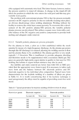
Arc stability and oxide removal are better than with TIG or MIG pro-
vided that the appropriate wave form is used. It is necessary to tailor each
wave form and the balance between DC electrode positive and DC
electrode negative to the individual alloy composition. Typical wave form
characteristics for the keyhole welding of a number of alloys are given
in Table 8.1. It is worth remembering that if the keyhole technique is
used autogenously the alloys must be capable of providing crack-free weld
metal.
Table 8.1 Typical parameters for keyhole welding of 6.5mm thick Al alloys
Aluminium grade Electrode negative Electrode positive
Current (A) Time (ms) Current (A) Time (ms)
2219 140 20 185 3
3001 155 20 220 3
5086 145 20 180 3
5456 130 20 185 3
6061 150 20 210 3