
Page 229 - Welding of Aluminium and its Alloys
P. 229
Weld defects and quality control 209
Cathode Ray Tube
Transmission (CRT) DISPLAY Defect indications
pulse indication SCREEN
Horizontal CRT beam
deflection Vertical CRT
beam deflection
TIME AMPLIFIER
BASE
Electrical impulse
for pulse initiation Signal from reflected
pulse (echo signal)
PULSE
OSCILLATOR
GENERATOR
Signal base from time
Ultrasonic Test Set
Probe
(transmitter/receiver)
Reflected pulses
from defects
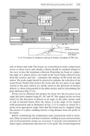
11.11 Principles of ultrasonic testing of metals. Courtesy of TWI Ltd.
lack of fusion and voids. The beams are transmitted as either compression
waves or shear waves and, ideally, a defect should be oriented normal to
the wave to give the maximum reflection. Projecting the beam at a glanc-
ing angle at a planar defect can result in the beam being reflected away
from the receiver and lost – remember the analogy of the torch and the
mirror.The probe angle should be selected to optimise the reflection of the
sound beam. Probes that project the beam into the test piece at an angle
normal to the plate surface are ideally suited to the detection of laminar
defects, i.e. those lying parallel to the plate surface and for determining the
plate thickness (Fig. 11.12).
Probes can be obtained that project the beam into the test piece at an
angle, the most common being 45°, 60° and 70°. The angled probes are best
suited for the detection of defects at an angle to the plate surface such
as lack of sidewall fusion. Here the defect is at the angle of the original
weld preparation and as illustrated in Fig. 11.13 is easiest to detect by a
probe of an appropriate angle. Note that the beam may be ‘skipped’ along
the interior of a plate, enabling defects a long distance from the probe to
be found.
Before commencing the examination some preparation work is neces-
sary. Data on material and heat treatment, welding process and procedure
and weld preparation design are necessary if accurate determinations of
defect types, orientations and sizes are to be made. The normal inspection