
Page 96 - Welding of Aluminium and its Alloys
P. 96
Welding design 85
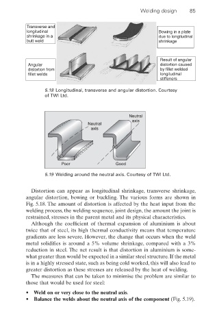
Transverse and
longitudinal Bowing in a plate
shrinkage in a due to longitudinal
butt weld shrinkage
Result of angular
Angular distortion caused
distortion from by fillet welded
fillet welds longitudinal
stiffeners
5.18 Longitudinal, transverse and angular distortion. Courtesy
of TWI Ltd.
Neutral
axis
Neutral
axis
Poor Good
5.19 Welding around the neutral axis. Courtesy of TWI Ltd.
Distortion can appear as longitudinal shrinkage, transverse shrinkage,
angular distortion, bowing or buckling. The various forms are shown in
Fig. 5.18. The amount of distortion is affected by the heat input from the
welding process, the welding sequence, joint design, the amount the joint is
restrained, stresses in the parent metal and its physical characteristics.
Although the coefficient of thermal expansion of aluminium is about
twice that of steel, its high thermal conductivity means that temperature
gradients are less severe. However, the change that occurs when the weld
metal solidifies is around a 5% volume shrinkage, compared with a 3%
reduction in steel. The net result is that distortion in aluminium is some-
what greater than would be expected in a similar steel structure. If the metal
is in a highly stressed state, such as being cold worked, this will also lead to
greater distortion as these stresses are released by the heat of welding.
The measures that can be taken to minimise the problem are similar to
those that would be used for steel:
• Weld on or very close to the neutral axis.
• Balance the welds about the neutral axis of the component (Fig. 5.19).