
Page 1064 - The Mechatronics Handbook
P. 1064
called IEEE 488.2 Standard Codes, Formats, Protocols, and Common Commands for Use with IEEE 488.1
(1987) [13], where IEEE 488.1 is the new name for the original IEEE 488 standard.
The IEEE 488.2 compliant devices must present data through data formats and codes specified in the
standard. The standard also specifies a minimum set of mandatory control sequences or commands and
suggests a few other optional commands. It also provides a standard status-reporting model that must
be implemented by the instrument manufacturers so that determining the status of instruments will be
easier for the instrument programmers.
Although not yet a standard, The Standard Commands for Programmable Instrumentation (SCPI)
put together in 1990 agrees upon a standard set of commands for various instrument categories. Accord-
ingly, all digital voltmeters manufactured by different manufacturers will respond to the same GPIB
command.
GPIB Hardware
This section describes the electrical and mechanical specifications of the GPIB interface as well as the
signal description and their purpose.
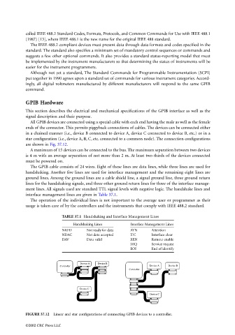
All GPIB devices are connected using a special cable with each end having the male as well as the female
ends of the connector. This permits piggyback connections of cables. The devices can be connected either
in a chained manner (i.e., device B connected to device A, device C connected to device B, etc.) or in a
star configuration (i.e., device A, B, C, etc. connected to a common node). The connection configurations
are shown in Fig. 37.12.
A maximum of 15 devices can be connected to the bus. The maximum separation between two devices
is 4 m with an average separation of not more than 2 m. At least two-thirds of the devices connected
must be powered on.
The GPIB cable consists of 24 wires. Eight of these lines are data lines, while three lines are used for
handshaking. Another five lines are used for interface management and the remaining eight lines are
ground lines. Among the ground lines are a cable shield line, a signal ground line, three ground return
lines for the handshaking signals, and three other ground return lines for three of the interface manage-
ment lines. All signals used are standard TTL signal levels with negative logic. The handshake lines and
interface management lines are given in Table 37.1.
The operation of the individual lines is not important to the average user or programmer as their
usage is taken care of by the controllers and the instruments that comply with IEEE 488.2 standard.
TABLE 37.1 Handshaking and Interface Management Lines
Handshaking Lines Interface Management Lines
NRFD Not ready for data ATN Attention
NDAC Not data accepted IFC Interface clear
DAV Data valid REN Remote enable
SRQ Service request
EOI End of identify
Device A Device B
Controller Device A Device B
Controller
Device C
Device C
FIGURE 37.12 Linear and star configurations of connecting GPIB devices to a controller.
©2002 CRC Press LLC