Page 1061 - The Mechatronics Handbook
P. 1061

PG
                                                           1                          1
                                                                        TxD
                                                           2                          2
                                                                        RxD
                                                           3            RTS           3
                                                          DTE   4       DSR           4  5   DCE
                                                                        CTS
                                                           5
                                                           6                          6
                                                                        SG
                                                           7                          7
                                                                        DCD
                                                           8                          8
                                                                        DTR
                                                           20                         20
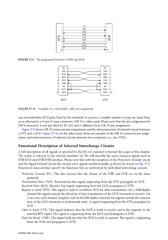
                                 FIGURE 37.9  Pin assignment between a DTE and DCE.
                                                         1   PG                      PG   1
                                                         2  TxD                     TxD   2
                                                         3   RxD                    RxD   3
                                                         4  RTS                     RTS   4
                                                         5   CTS                    CTS   5
                                                         6   DSR                    DSR   6
                                                         7   SG                      SG  7
                                                         8   DCD                    DCD  8
                                                        20  DTR                     DTR   20
                                                           DTE                      DTE

                                 FIGURE 37.10  Example of a null modem cable pin assignment.


                                 can accommodate all 25 pins, listed in the standard. In practice, a smaller number of pins are used; thus,
                                 as an alternative, a 9-pin D-type connector (DB-9) is often used. Please note that the pin assignment for
                                 DB-9 connector is not specified by RS-232 and is different from DB-25 pin assignment.
                                   Figure 37.9 shows DB-25 connector pin assignments and the interconnection of selected circuits between
                                 a DTE and a DCE. Figure 37.10, on the other hand, shows an example of the DB-25 connector pin assign-
                                 ments and interconnection of selected circuits between two computers, i.e., two DTEs.

                                 Functional Description of Selected Interchange Circuits
                                 A full description of all signals as specified by the RS-232 standard is beyond the scope of this chapter.
                                 The reader is referred to the relevant standard [4]. We will describe the most common signals used in
                                 DTE/DCE and DTE/DTE interface. Please note that with the exception of the Protective Ground circuit
                                 and the Signal Ground circuit the circuits carry signals unidirectionally, as shown by arrows in Fig. 37.9.
                                 Functional characteristics specify the functions that are performed by individual interchange circuits.

                                   Protective Ground (PG). This line ensures that the chassis of the DTE and DCE are on the same
                                       potential.
                                   Transmitted Data (TxD). Transmission line-signal originating from the DTE propagates to DCE.
                                   Received Data (RxD). Receiver line-signal originating from the DCE propagates to DTE.
                                   Request to Send (RTS). This signal is used to condition DCE for data transmission. On a half-duplex
                                       channel the signal controls the direction of data transmission of the DCE (transmit or receive). On
                                       a one-way-only channel (simplex) and on the full-duplex channels this signal controls the transmit
                                       state of the DCE (transmit or nontransmit state). A signal originating from the DTE propagates to
                                       DCE.
                                   Clear to Send (CTS). This signal indicates that the DCE is ready to receive and is the response to the
                                       asserted RTS signal. The signal is originating from the DCE and propagates to DTE.
                                   Data Set Ready (DSR). This signal indicates that the DCE is ready to operate. The signal is originating
                                       from the DCE and propagates to DTE.


                                 ©2002 CRC Press LLC
   1056   1057   1058   1059   1060   1061   1062   1063   1064   1065   1066