
Page 1057 - The Mechatronics Handbook
P. 1057
D R
R D
FIGURE 37.2 Example of an unbalanced data transmission.
D T R
R T D
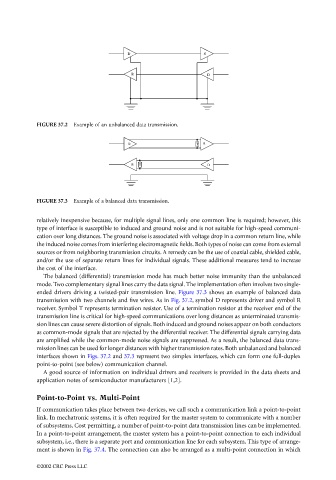
FIGURE 37.3 Example of a balanced data transmission.
relatively inexpensive because, for multiple signal lines, only one common line is required; however, this
type of interface is susceptible to induced and ground noise and is not suitable for high-speed communi-
cation over long distances. The ground noise is associated with voltage drop in a common return line, while
the induced noise comes from interfering electromagnetic fields. Both types of noise can come from external
sources or from neighboring transmission circuits. A remedy can be the use of coaxial cable, shielded cable,
and/or the use of separate return lines for individual signals. These additional measures tend to increase
the cost of the interface.
The balanced (differential) transmission mode has much better noise immunity than the unbalanced
mode. Two complementary signal lines carry the data signal. The implementation often involves two single-
ended drivers driving a twisted-pair transmission line. Figure 37.3 shows an example of balanced data
transmission with two channels and five wires. As in Fig. 37.2, symbol D represents driver and symbol R
receiver. Symbol T represents termination resistor. Use of a termination resistor at the receiver end of the
transmission line is critical for high-speed communications over long distances as unterminated transmis-
sion lines can cause severe distortion of signals. Both induced and ground noises appear on both conductors
as common-mode signals that are rejected by the differential receiver. The differential signals carrying data
are amplified while the common-mode noise signals are suppressed. As a result, the balanced data trans-
mission lines can be used for longer distances with higher transmission rates. Both unbalanced and balanced
interfaces shown in Figs. 37.2 and 37.3 represent two simplex interfaces, which can form one full-duplex
point-to-point (see below) communication channel.
A good source of information on individual drivers and receivers is provided in the data sheets and
application notes of semiconductor manufacturers [1,2].
Point-to-Point vs. Multi-Point
If communication takes place between two devices, we call such a communication link a point-to-point
link. In mechatronic systems, it is often required for the master system to communicate with a number
of subsystems. Cost permitting, a number of point-to-point data transmission lines can be implemented.
In a point-to-point arrangement, the master system has a point-to-point connection to each individual
subsystem, i.e., there is a separate port and communication line for each subsystem. This type of arrange-
ment is shown in Fig. 37.4. The connection can also be arranged as a multi-point connection in which
©2002 CRC Press LLC