
Page 1059 - The Mechatronics Handbook
P. 1059
is always indicated by the start bit, which has logical value 0 (also called “SPACE”). The start bit is followed
by 5–8 data bits representing a character. The data bits are followed by an optional parity bit. The stream
is terminated by one or two stop bits with logical value 1, which can be followed by idle line or the start
bit of the next character. The idle line corresponds to logical state 1. A parity bit is an extra bit inserted
after the data bits and before the stop bit(s). It is set according to the parity information of the data in
the stream. For example, if an even parity is used, the parity bit is set such that total number of ones in
the data stream including the parity bit is even. The parity bit is used by the receiver for error checking.
The task of the receiver is to detect the start of the data stream and to correctly sample individual bits
in the stream. After the detection of the start bit the receiver should sample individual bits, ideally at the
mid point of each bit, as shown in Fig. 37.6. In the case of an ideal sampling, as shown in Fig. 37.6, the
receiver is said to have distortion tolerance of 50%. In practice, the receiver of a UART is sampling
incoming signals using the Baud Rate Generator frequency, which is 16 times higher than the corre-
sponding baud rate used for transmission. The uncertainty in the detection of the start bit will reduce
the distortion tolerance by 6.25% (1/16) to 43.75% [3].
If, for example, the receiver clock is 1% slower than the clock of the corresponding transmitter, the
sampling time of the first data bit will be delayed by 1.5% of the bit time and the sampling time of the
stop bit will be delayed by 9.5%. In this case, the distortion tolerance would be further reduced to 34.25%.
If the receiver clock is slower by 5%, then the receiver may detect the start bit of the next character instead
of the stop bit of the current character. This results in a framing error. The above example shows the
significance of the accuracy of the clock speed and the reason why the data stream must be kept short
in asynchronous transmission.
Other factors affecting the error-free communications include length and type of transmission line, speed
of communications, parameters of line drivers, termination of transmission line, and the level of noise in
the communication system.
The Universal Asynchronous Receiver Transmitter (UART)
The basic function of the UART is to facilitate parallel-to-serial and serial-to-parallel data conversion.
The UART usually contains one transmitter and one receiver. The receiver and transmitter can operate
simultaneously and independently. The UART can operate in full-duplex or half-duplex mode.
Parallel data from the host computer are converted to an asynchronous serial bit stream. The UART
automatically adds a start bit, an optional parity bit, and the programmed number of stop bits, and sends
the stream out through the transmitter serial data output (TxD) output pin. The parallel data are con-
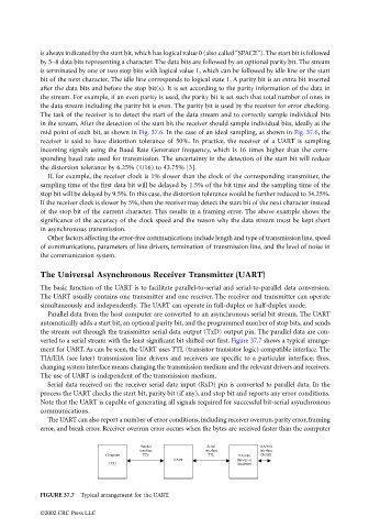
verted to a serial stream with the least significant bit shifted out first. Figure 37.7 shows a typical arrange-
ment for UART. As can be seen, the UART uses TTL (transistor transistor logic) compatible interface. The
TIA/EIA (see later) transmission line drivers and receivers are specific to a particular interface; thus,
changing system interface means changing the transmission medium and the relevant drivers and receivers.
The use of UART is independent of the transmission medium.
Serial data received on the receiver serial data input (RxD) pin is converted to parallel data. In the
process the UART checks the start bit, parity bit (if any), and stop bit and reports any error conditions.
Note that the UART is capable of generating all signals required for successful bit-serial asynchronous
communications.
The UART can also report a number of error conditions, including receiver overrun, parity error, framing
error, and break error. Receiver overrun error occurs when the bytes are received faster than the computer
Parallel Serial TIA/EIA
Interface Interface Interface
Computer TTL TTL TIA/EIA (Serial)
CPU UART Drivers or
Receivers
FIGURE 37.7 Typical arrangement for the UART.
©2002 CRC Press LLC