
Page 1055 - The Mechatronics Handbook
P. 1055
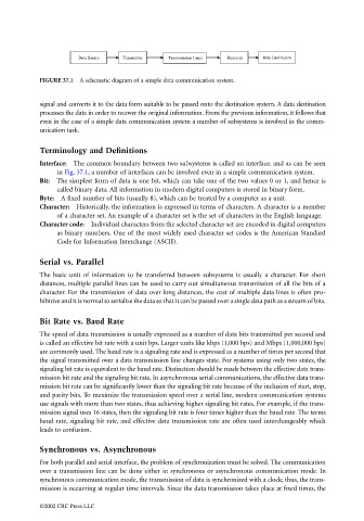
Data Source   Transmitter   Transmission Lines   Receiver   Data Destination


                                 FIGURE 37.1  A schematic diagram of a simple data communication system.


                                 signal and converts it to the data form suitable to be passed onto the destination system. A data destination
                                 processes the data in order to recover the original information. From the previous information, it follows that
                                 even in the case of a simple data communication system a number of subsystems is involved in the comm-
                                 unication task.

                                 Terminology and Definitions

                                 Interface: The common boundary between two subsystems is called an interface, and as can be seen
                                      in Fig. 37.1, a number of interfaces can be involved even in a simple communication system.
                                 Bit: The simplest form of data is one bit, which can take one of the two values 0 or 1, and hence is
                                      called binary data. All information in modern digital computers is stored in binary form.
                                 Byte: A fixed number of bits (usually 8), which can be treated by a computer as a unit.
                                 Character:  Historically, the information is expressed in terms of characters. A character is a member
                                      of a character set. An example of a character set is the set of characters in the English language.
                                 Character code: Individual characters from the selected character set are encoded in digital computers
                                      as binary numbers. One of the most widely used character set codes is the American Standard
                                      Code for Information Interchange (ASCII).


                                 Serial vs. Parallel
                                 The basic unit of information to be transferred between subsystems is usually a character. For short
                                 distances, multiple parallel lines can be used to carry out simultaneous transmission of all the bits of a
                                 character. For the transmission of data over long distances, the cost of multiple data lines is often pro-
                                 hibitive and it is normal to serialize the data so that it can be passed over a single data path as a stream of bits.

                                 Bit Rate vs. Baud Rate
                                 The speed of data transmission is usually expressed as a number of data bits transmitted per second and
                                 is called an effective bit rate with a unit bps. Larger units like kbps (1,000 bps) and Mbps (1,000,000 bps)
                                 are commonly used. The baud rate is a signaling rate and is expressed as a number of times per second that
                                 the signal transmitted over a data transmission line changes state. For systems using only two states, the
                                 signaling bit rate is equivalent to the baud rate. Distinction should be made between the effective data trans-
                                 mission bit rate and the signaling bit rate. In asynchronous serial communications, the effective data trans-
                                 mission bit rate can be significantly lower than the signaling bit rate because of the inclusion of start, stop,
                                 and parity bits. To maximize the transmission speed over a serial line, modern communication systems
                                 use signals with more than two states, thus achieving higher signaling bit rates. For example, if the trans-
                                 mission signal uses 16 states, then the signaling bit rate is four times higher than the baud rate. The terms
                                 baud rate, signaling bit rate, and effective data transmission rate are often used interchangeably which
                                 leads to confusion.

                                 Synchronous vs. Asynchronous
                                 For both parallel and serial interface, the problem of synchronization must be solved. The communication

                                 over a transmission line can be done either in synchronous or asynchronous communication mode. In
                                 synchronous communication mode, the transmission of data is synchronized with a clock; thus, the trans-
                                 mission is occurring at regular time intervals. Since the data transmission takes place at fixed times, the

                                 ©2002 CRC Press LLC