
Page 1060 - The Mechatronics Handbook
P. 1060
processes them. The parity error is indicated if the parity of the bit stream changed during the commu-
nication process. Framing error is reported if the sampled stop bit is not at logic 1 level. The break error
is reported if the communication line is idle for the time equivalent to the duration of at least one character.
Older types of UART devices such as 8250, 16450 had only one byte FIFO (first in first out) buffer and
thus it was easy to overrun the receiver buffer. More recent devices are equipped with larger buffers providing
more efficient communications. For example, device 16550D from National Semiconductor has a 16-byte
receiver buffer and a 16-byte transmitter buffer and can operate at speeds up to 1.5 Mbps. Modern UARTs
can also automatically handle tasks pertaining to multi-drop systems on a network.
37.2 TIA/EIA Serial Interface Standards
RS-232 Serial Interface
The RS-232 (Recommended Standard) was originally developed in 1962 by the Electronic Industries
Association (EIA) as an interface between a computer and communication equipment. It is now jointly
maintained by the Telecommunication Industries Association (TIA) and the EIA. The current version is
designated as TIA/EIA 232-F (sixth revision) [4]. The Consulting Committee for International Telegraphs
and Telephones (CCITT) issues recommendations that cover interfaces equivalent or similar to those
issued by TIA/EIA.
Rapid development of computers created a demand for computer-to-computer communications over
long distances. The switched public telephone network provided a readily available infrastructure for the
communication task. Because computers generate digital data while the telephone network was designed
for the transmission of voice signal, the digital signals from the computer had to be converted to a mod-
ulated signal which can be transmitted over the analog network. Modems (modulator/demodulator) are
used to convert the digital signal into a modulated analog signal that is transmitted over the telephone line
and converted back to digital signal by the modem at the other end of the telephone line. The RS-232 was
designed as an interface between a computer and a modem. The formal name of the RS-232 standard is
“Interface Between Data Terminal Equipment and Data Communication Equipment Employing Serial
Binary Data Interchange,” in which the Data Terminal Equipment (DTE) represents the computer and
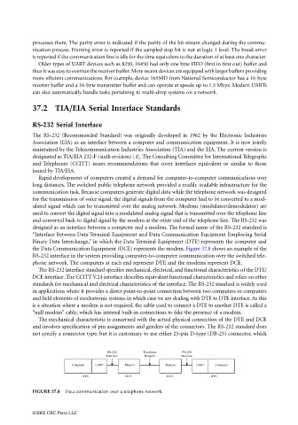
the Data Communication Equipment (DCE) represents the modem. Figure 37.8 shows an example of the
RS-232 interface in the system providing computer-to-computer communication over the switched tele-
phone network. The computers at each end represent DTE and the modems represent DCE.
The RS-232 interface standard specifies mechanical, electrical, and functional characteristics of the DTE/
DCE interface. The CCITT V.24 interface describes equivalent functional characteristics and relies on other
standards for mechanical and electrical characteristics of the interface. The RS-232 standard is widely used
in applications where it provides a direct point-to-point connection between two computers or computers
and field elements of mechatronic systems in which case we are dealing with DTE to DTE interface. As this
is a situation where a modem is not required, the cable used to connect a DTE to another DTE is called a
“null modem” cable, which has internal built-in connections to fake the presence of a modem.
The mechanical characteristic is concerned with the actual physical connection of the DTE and DCE
and involves specification of pin assignments and genders of the connectors. The RS-232 standard does
not specify a connector type, but it is customary to use either 25-pin D-type (DB-25) connector, which
RS-232 Telephone RS-232
Interface Network Interface
Computer UART Modem Modem UART Computer
DTE DCE DCE DTE
FIGURE 37.8 Data communication over a telephone network.
©2002 CRC Press LLC