
Page 1058 - The Mechatronics Handbook
P. 1058
Master
System
Slave Slave Slave Slave
System 1 System 2 System 3 System 4
FIGURE 37.4 A point-to-point communication system with four subsystems.
System 1 System 2 System 3 System 4
FIGURE 37.5 A multi-point communication system.
Ideal Sampling points
(center of bit)
1
0
Start Data Data Data Data Data Data Data Data Stop Start
Bit Bit 0 Bit 1 Bit 2 Bit 3 Bit 4 Bit 5 Bit 6 Bit 7 Bit Bit
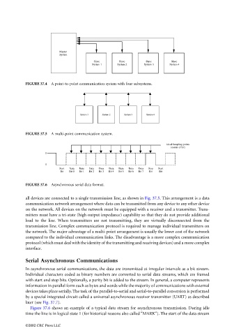
FIGURE 37.6 Asynchronous serial data format.
all devices are connected to a single transmission line, as shown in Fig. 37.5. This arrangement is a data
communication network arrangement where data can be transmitted from any device to any other device
on the network. All devices on the network must be equipped with a receiver and a transmitter. Trans-
mitters must have a tri-state (high output impedance) capability so that they do not provide additional
load to the line. When transmitters are not transmitting, they are virtually disconnected from the
transmission line. Complex communication protocol is required to manage individual transmitters on
the network. The major advantage of a multi-point arrangement is usually the lower cost of the network
compared to the individual communication links. The disadvantage is a more complex communication
protocol (which must deal with the identity of the transmitting and receiving devices) and a more complex
interface.
Serial Asynchronous Communications
In asynchronous serial communications, the data are transmitted at irregular intervals as a bit stream.
Individual characters coded as binary numbers are converted to serial data streams, which are framed
with start and stop bits. Optionally, a parity bit is added to the stream. In general, a computer represents
information in parallel form such as bytes and words while the majority of communications with external
devices takes place serially. The task of the parallel-to-serial and serial-to-parallel conversion is performed
by a special integrated circuit called a universal asynchronous receiver transmitter (UART) as described
later (see Fig. 37.7).
Figure 37.6 shows an example of a typical data stream for asynchronous transmission. During idle
time the line is in logical state 1 (for historical reasons also called “MARK”). The start of the data stream
©2002 CRC Press LLC