
Page 115 - The Mechatronics Handbook
P. 115
0066_Frame_C08 Page 6 Wednesday, January 9, 2002 3:48 PM
the only nonzero elements are
d 113 , d 223 , d 333 , d 232 = d 322 , d 131 = d 313 , d 123 = d 213 .
Numerical values for the coefficients in (8.22) for bulk BaTiO 3 crystals can be found in [Zgonik et al. 1994].
8.2 Common Structures in Mechatronic Systems
Microelectromechanical systems (MEMS) traditionally use technology developed for the manufacturing
of integrated circuits. As a result, the employed mechanical structures are often planar devices—springs,
coils, bridges, or cantilever beams, subjected to in-plane and out-of-plane bending and torsion. Using
high aspect ratio reactive ion etching combined with fusion bonding of silicon, it is possible to realize
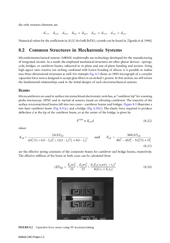
true three-dimensional structures as well. For example Fig. 8.2 shows an SEM micrograph of a complex
capacitive force sensor designed to accept glass fibers in an etched v-groove. In this section, we will review
the fundamental relationships used in the initial designs of such electromechanical systems.
Beams
Microcantilevers are used in surface micromachined electrostatic switches, as “cantilever tip” for scanning
probe microscopy (SPM) and in myriad of sensors, based on vibrating cantilevers. The majority of the
surface micromachined beams fall into two cases—cantilever beams and bridges. Figure 8.3 illustrates a
two-layer cantilever beam (Fig. 8.3(a)) and a bridge (Fig. 8.3(b)). The elastic force required to produce
deflection d at the tip of the cantilever beam, or at the center of the bridge, is given by
elast
F = K d (8.22)
eff
where
( (
K eff = ---------------------------------------------------------------------------------------------------------- and K eff = -------------------------------------------------------------
24 EI) eff
360 EI) eff
(
(
( 6l e /5) + 6 ll e )l e + 12 ll e ) l e + 8 ll e ) 3 30l – 45ll e – 5 l e /l) + 3l e 3
(
(
2
3
2
4
2
3
–
–
–
(8.23)
are the effective spring constants of the composite beams for cantilever and bridge beams, respectively.
The effective stiffness of the beam in both cases can be calculated from
(
3 3 E 1 E 2 t 1 t 2 wt 1 + ) 2
( EI) eff = ------------- + ------------- + -------------------------------------------- (8.24)
E 1 wt 1
E 2 wt 2
t 2
(
12 12 4 E 1 t 1 + E 2 t 2 )
FIGURE 8.2 Capacitive force sensor using 3D micromachining.
©2002 CRC Press LLC