Page 117 - The Mechatronics Handbook
P. 117

0066_Frame_C08  Page 8  Wednesday, January 9, 2002  3:48 PM


                             TABLE 8.2  Deflection and Bending Moments of Clamped Plate Under Uniform Load q
                             [Evans 1939]
                             b/a  W(x = 0, y = 0)  M x (x = a/2, y = 0)  M y (x = 0, y = b/2)  M x (x = 0, y = 0)  M y (x = 0, y = 0)
                                         4
                             1     0.00126qa /D   −0.0513qa  2   −0.0513qa  2   0.0231qa 2   0.0231qa 2
                                         4
                             1.5   0.00220qa /D   −0.0757qa  2   −0.0570qa  2   0.0368qa 2   0.0203qa 2
                                         4
                             2     0.00254qa /D   −0.0829qa  2   −0.0571qa  2   0.0412qa 2   0.0158qa 2
                                         4
                             ∞     0.00260qa /D   −0.0833qa  2   −0.0571qa  2   0.0417qa 2   0.0125qa 2


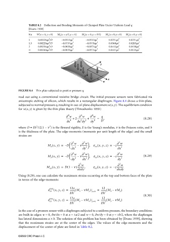
                       FIGURE 8.4  Thin plate subjected to positive pressure q.
                       read out using a conventional resistive bridge circuit. The initial pressure sensors were fabricated via
                       anisotropic etching of silicon, which results in a rectangular diaphragm. Figure 8.4 shows a thin-plate,
                       subjected to normal pressure q, resulting in out-of-plane displacement w(x, y). The equilibrium condition
                       for w(x, y) is given by the thin plate theory [Timoshenko 1959]:

                                                    4       4     4
                                                                        q
                                                          ∂ w
                                                   ∂ w  2---------------- +  ∂ w  ----,          (8.28)
                                                                 --------- =
                                                   --------- +
                                                           2
                                                   ∂x  4  ∂x ∂y  2  ∂y  4  D
                                 3
                                         2
                       where D = Eh /12(1 − ν ) is the flexural rigidity, E is the Young’s modulus, ν is the Poisson ratio, and h
                       is the thickness of the plate. The edge-moments (moments per unit length of the edge) and the small
                       strains are
                                                                                  2
                                                             2
                                                       2
                                                     
                                                               
                                                                                 ∂ w
                                                      ∂ w
                                                            ∂ w
                                                                     (
                                        M x x, y(  ) =  – D --------- –  n--------- , e xx x, y, z) =  – z---------
                                                     
                                                               2 
                                                      ∂x 2  ∂y                   ∂x  2
                                                                                  2
                                                       2
                                                             2
                                                               
                                                     
                                                            ∂ w
                                                                                 ∂ w
                                                      ∂ w
                                                                     (
                                        M y x, y) =  – D --------- –  n--------- ,  e yy x, y, z) =  – z---------  (8.29)
                                          (
                                                     
                                                               2 
                                                      ∂y 2  ∂x                   ∂y  2
                                                           2
                                                                                  2
                                                          ∂ w
                                                                                 ∂ w
                                          (
                                       M xy x, y) =  D(1 n)------------,  e xy x, y, z) =  – z------------
                                                                     (
                                                      –
                                                         ∂x∂y                    ∂x∂y
                       Using (8.29), one can calculate the maximum strains occurring at the top and bottom faces of the plate
                       in terms of the edge-moments:
                                                                        12
                                        e xx x, y, z(  ) =  12z  nM y )  =  -------- M x –(  nM y )
                                                     -------- M x –(
                                         max
                                                     Eh 3         z=h  Eh 2
                                                                                                 (8.30)
                                                                        12
                                         max
                                           (
                                                     -------- M y –(
                                        e yy x, y, z) =  12z  nM x )  z=h  =  -------- M y –(  nM x )
                                                     Eh 3              Eh 2
                       In the case of a pressure sensor with a diaphragm subjected to a uniform pressure, the boundary conditions
                       are built-in edges: w = 0, ∂w/∂x = 0 at x = ±a/2 and w = 0, ∂w/∂y = 0 at y = ±b/2, where the diaphragm
                       has lateral dimensions a × b. The solution of this problem has been obtained by [Evans 1939], showing
                       that the maximum strains are at the center of the edges. The values of the edge-moments and the
                       displacement of the center of plate are listed in Table 8.2.
                       ©2002 CRC Press LLC
   112   113   114   115   116   117   118   119   120   121   122