
Page 122 - The Mechatronics Handbook
P. 122
0066_Frame_C08 Page 13 Wednesday, January 9, 2002 3:48 PM
d
A 2 A 1 nI
FIGURE 8.7 Electromagnetic actuation.
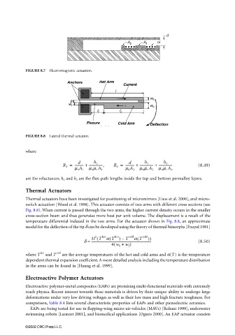
FIGURE 8.8 Lateral thermal actuator.
where
d
d
R 1 = ----------- + -----------------, R 2 = ----------- + ----------------- + ----------------- (8.49)
h 1
h 2
h 1
m 0 A 1 m 0 m r A 1 m 0 A 2 m 0 m r A 2 m 0 m r A b
are the reluctances; h 1 and h 2 are the flux-path lengths inside the top and bottom permalloy layers.
Thermal Actuators
Thermal actuators have been investigated for positioning of micromirrors [Liew et al. 2000], and micro-
switch actuation [Wood et al. 1998]. This actuator consists of two arms with different cross sections (see
Fig. 8.8). When current is passed through the two arms, the higher current density occurs in the smaller
cross-section beam and thus generates more heat per unit volume. The displacement is a result of the
temperature differential induced in the two arms. For the actuator shown in Fig. 8.8, an approximate
model for the deflection of the tip δ can be developed using the theory of thermal bimorphs [Faupel 1981]
2
(
(
–
d ≈ 3l T( hot a T hot ) T cold a T cold )) (8.50)
-----------------------------------------------------------------------------
4 w h + w f )
(
hot
where T and T cold are the average temperatures of the hot and cold arms and α(T ) is the temperature
dependent thermal expansion coefficient. A more detailed analysis including the temperature distribution
in the arms can be found in [Huang et al. 1999].
Electroactive Polymer Actuators
Electroactive polymer-metal composites (EAPs) are promising multi-functional materials with extremely
reach physics. Recent interest towards these materials is driven by their unique ability to undergo large
deformations under very low driving voltages as well as their low mass and high fracture toughness. For
comparison, Table 8.4 lists several characteristic properties of EAPs and other piezoelectric ceramics.
EAPs are being tested for use in flapping-wing micro-air-vehicles (MAVs) [Rohani 1999], underwater
swimming robots [Laurent 2001], and biomedical applications [Oguro 2000]. An EAP actuator consists
©2002 CRC Press LLC