Page 121 - The Mechatronics Handbook
P. 121

0066_Frame_C08  Page 12  Wednesday, January 9, 2002  3:48 PM


                                                    Deflection
                                                    2g 2g
                                                   2c  2c  2c
                                    x
                                      A      A     V    V  2d
                                     x > 0 Engaged
                                                   <Section A-A>
                                     x < 0 Seperated                       kV
                                               (a)                         (b)

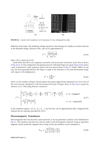
                       FIGURE 8.6  Lateral comb transducers: (a) Dimensions; (b) two orthogonal Si combs.

                       deflection of the beam. The minimum voltage required to close the gap of a cantilever actuator is known
                       as the threshold voltage [Petersen 1978], and can be approximated as

                                                               (     3
                                                       V ≈   18 IE) eff d 0                      (8.45)
                                                        th
                                                             --------------------------
                                                                  4
                                                              5e 0 L w
                       where (IE) eff  is given by (8.24).
                         Comb drives also fall in two categories: symmetric and asymmetric. Symmetric comb drive is shown
                       in Fig. 8.6(a). In this configuration the gaps between the individual fingers are equal. Figure 8.6(b) shows
                       a pair of asymmetric comb capacitors, used in the force sensor shown in Fig. 8.2 [Enikov 2000a]. In any
                       case, the force generated between the fingers is equal to the derivative of the total electrostatic energy
                       with respect to the displacement

                                                        F  el  =  n∂C  2                         (8.46)
                                                              ----------V
                                                              2 ∂x
                       where n is the number of fingers. Several authors have given approximate expressions for (8.46). One of
                       the most accurate calculations of the force between the pair of fingers shown in Fig. 8.6(a) is given by
                       [Johnson et al. 1995] using Schwartz transforms

                                    2
                                  e 0 V      c -- +    2  1 1 +  2g   1+c/g  +  pd  c +   x >  ∆ + engaged(  )
                                                     
                                                                         g
                                      
                                  ----------- ln  g    1   –     -----  ------ –  ----------  ,
                                                          c 
                                   p
                                                                        x
                                                                   g
                             el                                         
                           F   =                                                                (8.47)
                                   e 0 V  2 c +  g) 
                                         (
                                      2
                                  – ----------- -------------------  ,          x <  – ∆ − separated(  )
                                       
                                   p     x   
                                 
                       In the transition region x ∈[−∆ − ; ∆ + ], ∆ +,−  ≈ 2g, the force can be approximated with a tangential line
                       between the two branches described by (8.47).
                       Electromagnetic Transducers
                       Electromagnetic force has also been used extensively. It can be generated via planar coil as illustrated in
                       Fig. 8.7. The cantilever and often the coils are made of soft ferromagnetic material. Using an equivalent
                       magnetic circuit model, the magnetic force acting on the top cantilever can be estimated as
                                                           2n I 2A 2 + A 1 )
                                                               (
                                                             2 2
                                                   F mag =  ---------------------------------------------  (8.48)
                                                          m 0 A 1 A 2 2R 1 +  R 2 ) 2
                                                                (
                       ©2002 CRC Press LLC
   116   117   118   119   120   121   122   123   124   125   126