
Page 171 - The Mechatronics Handbook
P. 171
0066-frame-C09 Page 45 Friday, January 18, 2002 11:01 AM
z
mV ω
I:m y z
y
p V
F x x mω V
x x
1 z G
mV ω mV ω
z y
y z mV ω
x z V
x y
(a) (b) (c)
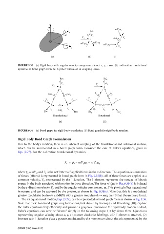
FIGURE 9.35 (a) Rigid body with angular velocity components about x, y, z axes. (b) x-direction translational
dynamics in bond graph form. (c) Gyrator realization of coupling forces.
I:m I:I x
V ω
F x x T x
x
1 1
mω mω h z h
z y y
G G G G
F F z T y T z
y
1 1 1 1
G G
V V ω h ω
y mω z y
I:m x I:m I:I y x z I:I z
Translational Rotational
(a) (b)
FIGURE 9.36 (a) Bond graph for rigid body translation. (b) Bond graph for rigid body rotation.
Rigid Body Bond Graph Formulation
Due to the body’s rotation, there is an inherent coupling of the translational and rotational motion,
which can be summarized in a bond graph form. Consider the case of Euler’s equations, given in
Eqs. (9.27). For the x-direction translational dynamics,
F x = p ˙ x – mV y ω z + mV z ω y
where p x = mV x , and F x is the net “external” applied forces in the x-direction. This equation, a summation
of forces (efforts) is represented in bond graph form in Fig. 9.35(b). All of these forces are applied at a
common velocity, V x , represented by the 1-junction. The I element represents the storage of kinetic
energy in the body associated with motion in the x-direction. The force mV y ω z in Fig. 9.35(b) is induced
by the y-direction velocity, V y , and by the angular velocity component, ω z . This physical effect is gyrational
in nature, and can be captured by the gyrator, as shown in Fig. 9.35(c). Note that this is a modulated
gyrator (could also be shown as MGY) with a gyrator modulus of r = mω z (verify that the units are force).
The six equations of motion, Eqs. (9.27), can be represented in bond graph form as shown in Fig. 9.36.
Note that these two bond graph ring formations, first shown by Karnopp and Rosenberg [18], capture
the Euler equations very efficiently and provide a graphical mnemonic for rigid body motion. Indeed,
Euler’s equations can now be “drawn” simply in the following steps: (1) lay down three 1-junctions
representing angular velocity about x, y, z (counter clockwise labeling), with I elements attached, (2)
between each 1-junction place a gyrator, modulated by the momentum about the axis represented by the
©2002 CRC Press LLC