
Page 277 - The Mechatronics Handbook
P. 277
• Will the computation be symbolic or numeric?
• Will use of an exact equation, nodal analysis, or finite element analysis be most appropriate?
Currently, these are the techniques which are favored by most MEMS developers.
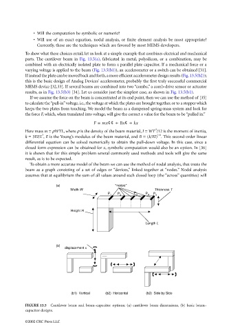
To show what these choices entail, let us look at a simple example that combines electrical and mechanical
parts. The cantilever beam in Fig. 13.5(a), fabricated in metal, polysilicon, or a combination, may be
combined with an electrically isolated plate to form a parallel plate capacitor. If a mechanical force or a
varying voltage is applied to the beam (Fig. 13.5(b1)), an accelerometer or a switch can be obtained [31].
If instead the plate can be moved back and forth, a more efficient accelerometer design results (Fig. 13.5(b2));
this is the basic design of Analog Devices’ accelerometer, probably the first truly successful commercial
MEMS device [32,33]. If several beams are combined into two “combs,” a comb-drive sensor or actuator
results, as in Fig. 13.5(b3) [34]. Let us consider just the simplest case, as shown in Fig. 13.5(b1).
If we assume the force on the beam is concentrated at its end point, then we can use the method of [35]
to calculate the “pull-in” voltage, i.e., the voltage at which the plates are brought together, or to a stopper which
keeps the two plates from touching. We model the beam as a dampened spring-mass system and look for
the force F, which, when translated into voltage, will give the correct x value for the beam to be “pulled in.”
F = mx¢¢ + Bx¢ + kx
3
Here mass m = ρWTL, where ρ is the density of the beam material, I = WT /12 is the moment of inertia,
3
1/4
k = 3EI/L , E is the Young’s modulus of the beam material, and B = (k/EI) . This second-order linear
differential equation can be solved numerically to obtain the pull-down voltage. In this case, since a
closed form expression can be obtained for x, symbolic computation would also be an option. In [36]
it is shown that for this simple problem several commonly used methods and tools will give the same
result, as is to be expected.
To obtain a more accurate model of the beam we can use the method of nodal analysis, that treats the
beam as a graph consisting of a set of edges or “devices,” linked together at “nodes.” Nodal analysis
assumes that at equilibrium the sum of all values around each closed loop (the “across” quantities) will
(a) “nodes”
Width W Thickness T
P 1 P 2 P 3 P 4 P 5
Height H
Length L
(b)
displacement x
(b1) Vertical (b2) Horizontal (b3) Side by Side
FIGURE 13.5 Cantilever beam and beam–capacitor options: (a) cantilever beam dimensions, (b) basic beam–
capacitor designs.
©2002 CRC Press LLC