
Page 410 - The Mechatronics Handbook
P. 410
0066_frame_C19 Page 32 Wednesday, January 9, 2002 5:17 PM
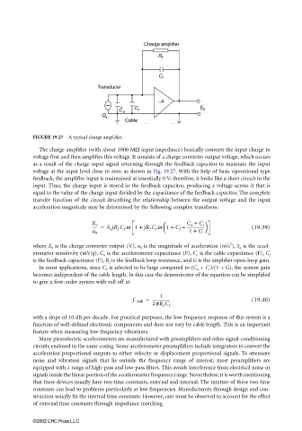
FIGURE 19.27 A typical charge amplifier.
The charge amplifier (with about 1000 MΩ input impedance) basically converts the input charge to
voltage first and then amplifies this voltage. It consists of a charge converter output voltage, which occurs
as a result of the charge input signal returning through the feedback capacitor to maintain the input
voltage at the input level close to zero, as shown in Fig. 19.27. With the help of basic operational-type
feedback, the amplifier input is maintained at essentially 0 V; therefore, it looks like a short circuit to the
input. Thus, the charge input is stored in the feedback capacitor, producing a voltage across it that is
equal to the value of the charge input divided by the capacitance of the feedback capacitor. The complete
transfer function of the circuit describing the relationship between the output voltage and the input
acceleration magnitude may be determined by the following complex transform:
----- = S a jR f C f w 1 + jR f C f w 1 + C f + C a + C c (19.39)
E 0
-----------------
a 0 1 + G
2
where E 0 is the charge converter output (V), a 0 is the magnitude of acceleration (m/s ), S a is the accel-
erometer sensitivity (mV/g), C a is the accelerometer capacitance (F), C c is the cable capacitance (F), C f
is the feedback capacitance (F), R f is the feedback loop resistance, and G is the amplifier open-loop gain.
In most applications, since C f is selected to be large compared to (C a + C c )/(1 + G), the system gain
becomes independent of the cable length. In this case the denominator of the equation can be simplified
to give a first-order system with roll off at
1
f −3dB = ----------------- (19.40)
2pR e C f
with a slope of 10 dB per decade. For practical purposes, the low-frequency response of this system is a
function of well-defined electronic components and does not vary by cable length. This is an important
feature when measuring low-frequency vibrations.
Many piezoelectric accelerometers are manufactured with preamplifiers and other signal-conditioning
circuits enclosed in the same casing. Some accelerometer preamplifiers include integrators to convert the
acceleration proportional outputs to either velocity or displacement proportional signals. To attenuate
noise and vibration signals that lie outside the frequency range of interest, most preamplifiers are
equipped with a range of high-pass and low-pass filters. This avoids interference from electrical noise or
signals inside the linear portion of the accelerometer frequency range. Nevertheless, it is worth mentioning
that these devices usually have two time constants, external and internal. The mixture of these two time
constants can lead to problems particularly at low frequencies. Manufacturers through design and con-
struction usually fix the internal time constants. However, care must be observed to account for the effect
of external time constants through impedance matching.
©2002 CRC Press LLC