
Page 411 - The Mechatronics Handbook
P. 411
0066_frame_C19 Page 33 Wednesday, January 9, 2002 5:17 PM
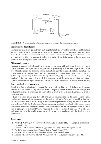
FIGURE 19.28 A typical signal conditioning arrangement for single chip microaccelerometers.
Piezoresistive Transducers
Piezoresistive transducers generally have high-amplitude outputs, low-output impedance, and low intrin-
sic noise. Most of these transducers are designed for constant-voltage excitations. They are usually
calibrated for constant-current excitations to avoid external interference. Many piezoresistive transducers
are configured as full-bridge devices. Some have four active piezoresistive arms, together with two fixed
precision resistors to permit shunt calibration.
Microaccelerometers
In microaccelerometers signal-conditioning circuitry is integrated within the same chip as the sensor. A
typical example of the signal-conditioning circuitry is given in Fig. 19.28 in block diagram form. In this
type of accelerometer, the electronic system is essentially a crystal-controlled oscillator circuit and the
output signal of the oscillator is a frequency-modulated acceleration signal. Some circuits provide a
buffered square-wave output that can be directly interfaced digitally. In these cases the need for analog-
to-digital (A/D) conversion is eliminated, thus removing one of the major sources of errors. In other
types of accelerometers, signal conditioning circuits such as A/D converters are retained within the chip.
Force Feedback Accelerometers
Signals from force feedback accelerometers often must be digitized for use in digital systems. A common
solution is to use voltage to frequency or current to frequency converters to convert the analog signals
to train pulses. These converters are expensive, often as much as the accelerometer, and add as much to
the error budget.
Here, it is worth mentioning that GPS systems are becoming add-ons to many position sensing
mechanisms. Because of antenna dynamics, shadowing, multipath effects, and to provide redundancy
for critical systems such as aircraft, many of these systems require inertial aiding, tied-in with accelerom-
eters and gyros. With the development of micromachining, small and cost-effective GPS assisted inertial
systems will be available in the near future. These developments will require extensive signal processing
with a high degree of accuracy. Dynamic ranges on the order of a million to one (e.g., 30–32 bits) need
to be dealt with. In order to achieve accuracy requirements, a great challenge awaits the signal processing
practitioner.
References
1. Bentley, J. P., Principles of Measurement Systems, 2nd ed., Burnt Mill, UK: Longman Scientific and
Technical, 1988.
2. Doebelin, E. O., Measurement Systems: Application and Design, 4th ed., Singapore: McGraw-Hill, 1990.
3. Frank, R., Understanding Smart Sensors, Boston: Artech House, 1996.
4. Harris, C., Shock and Vibration Handbook, 4th ed., McGraw-Hill, 1995.
5. Holman, J. P., Experimental Methods for Engineers, 5th ed., Singapore: McGraw-Hill, 1989.
©2002 CRC Press LLC