
Page 416 - The Mechatronics Handbook
P. 416
0066_frame_C19 Page 38 Wednesday, January 9, 2002 5:17 PM
Voltage recording
R g R device
Gage 2
C E o G
R
4 D R 3
E l
+ -
FIGURE 19.33 The Wheatstone bridge.
p
x 1 2
Top Bottom
1 h
Axial gages E o
3 1 and 3 Bottom Top
b 4 3
Axial gages +
2 and 4 on the -
bottom surface E l
(a) (b)
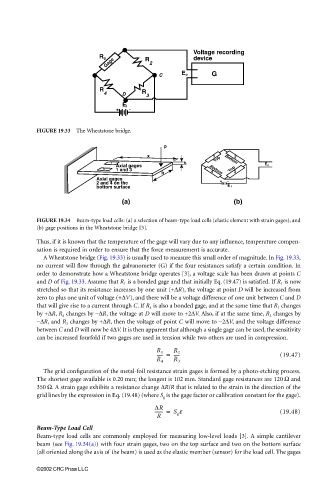
FIGURE 19.34 Beam-type load cells: (a) a selection of beam-type load cells (elastic element with strain gages), and
(b) gage positions in the Wheatstone bridge [3].
Thus, if it is known that the temperature of the gage will vary due to any influence, temperature compen-
sation is required in order to ensure that the force measurement is accurate.
A Wheatstone bridge (Fig. 19.33) is usually used to measure this small order of magnitude. In Fig. 19.33,
no current will flow through the galvanometer (G) if the four resistances satisfy a certain condition. In
order to demonstrate how a Wheatstone bridge operates [3], a voltage scale has been drawn at points C
and D of Fig. 19.33. Assume that R 1 is a bonded gage and that initially Eq. (19.47) is satisfied. If R 1 is now
stretched so that its resistance increases by one unit (+∆R), the voltage at point D will be increased from
zero to plus one unit of voltage (+∆V), and there will be a voltage difference of one unit between C and D
that will give rise to a current through C. If R 4 is also a bonded gage, and at the same time that R 1 changes
by +∆R, R 4 changes by −∆R, the voltage at D will move to +2∆V. Also, if at the same time, R 2 changes by
−∆R, and R 3 changes by +∆R, then the voltage of point C will move to −2∆V, and the voltage difference
between C and D will now be 4∆V. It is then apparent that although a single gage can be used, the sensitivity
can be increased fourfold if two gages are used in tension while two others are used in compression.
----- = R 2 (19.47)
R 1
-----
R 4 R 3
The grid configuration of the metal-foil resistance strain gages is formed by a photo-etching process.
The shortest gage available is 0.20 mm; the longest is 102 mm. Standard gage resistances are 120 Ω and
350 Ω. A strain gage exhibits a resistance change ∆R/R that is related to the strain in the direction of the
grid lines by the expression in Eq. (19.48) (where S g is the gage factor or calibration constant for the gage).
∆R S g ε (19.48)
------- =
R
Beam-Type Load Cell
Beam-type load cells are commonly employed for measuring low-level loads [3]. A simple cantilever
beam (see Fig. 19.34(a)) with four strain gages, two on the top surface and two on the bottom surface
(all oriented along the axis of the beam) is used as the elastic member (sensor) for the load cell. The gages
©2002 CRC Press LLC