
Page 417 - The Mechatronics Handbook
P. 417
0066_frame_C19 Page 39 Wednesday, January 9, 2002 5:17 PM
are wired into a Wheatstone bridge as shown in Fig. 19.34(b). The load P produces a moment M = Px at
the gage location (x) that results in the following strains:
6M
6Px
e 1 = – e 2 = e 3 = – e 4 = ----------- = ----------- (19.49)
Ebh 2 Ebh 2
where b is the width of the cross-section of the beam and h is the height of the cross-section of the beam.
Thus, the response of the strain gages is obtained from Eq. (19.50).
6S g Px
--------- = – --------- = --------- = – --------- = -------------- (19.50)
∆R 1
∆R 4
∆R 3
∆R 2
Ebh
R 1 R 2 R 3 R 4 2
The output voltage E o from the Wheatstone bridge, resulting from application of the load P, is obtained
from Eq. (19.51). If the four strain gages on the beam are assumed to be identical, then Eq. (19.51) holds.
E o = 6S g PxE 1 (19.51)
--------------------
Ebh 2
The range and sensitivity of a beam-type load cell depends on the shape of the cross-section of the beam,
the location of the point of application of the load, and the fatigue strength of the material from which
the beam is fabricated.
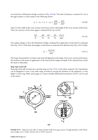
Ring-Type Load Cell
Ring-type load cells incorporate a proving ring (see Fig. 19.35) as the elastic element. The ring element
can be designed to cover a very wide range of loads by varying the diameter D, the thickness t, or the
depth w of the ring. Either strain gages or a linear variable-differential transformer (LVDT) can be used
as the sensor.
FIGURE 19.35 Ring-type load cells: (a) elastic element with strain-gage sensors; (b) gage positions in the Wheat-
stone bridge; and (c) elastic element with an LVDT sensor [3].
©2002 CRC Press LLC