
Page 422 - The Mechatronics Handbook
P. 422
0066_frame_C19 Page 44 Wednesday, January 9, 2002 5:17 PM
A capacitance sensor consists of two metal plates separated by an air gap. The capacitance C between
terminals is given by the expression:
C = e o e r A (19.57)
---
h
where
C = capacitance in farads (F),
ε o = dielectric constant of free space,
ε r = relative dielectric constant of the insulator,
A = overlapping area for the two plates,
h = thickness of the gap between the two plates.
The sensitivity of capacitance-type sensors is inherently low. Theoretically, decreasing the gap h should
increase the sensitivity; however, there are practical electrical and mechanical conditions that preclude
high sensitivities. One of the main advantages of the capacitive transducer is that moving of one of its
plates relative to the other requires an extremely small force to be applied. A second advantage is stability
and the sensitivity of the sensor is not influenced by pressure or temperature of the environment.
Force Sensing Resistors (Conductive Polymers)
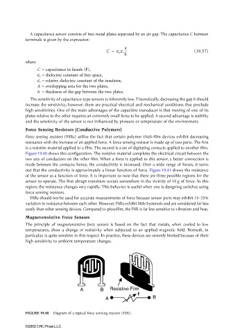
Force sensing resistors (FSRs) utilize the fact that certain polymer thick-film devices exhibit decreasing
resistance with the increase of an applied force. A force sensing resistor is made up of two parts. The first
is a resistive material applied to a film. The second is a set of digitating contacts applied to another film.
Figure 19.40 shows this configuration. The resistive material completes the electrical circuit between the
two sets of conductors on the other film. When a force is applied to this sensor, a better connection is
made between the contacts; hence, the conductivity is increased. Over a wide range of forces, it turns
out that the conductivity is approximately a linear function of force. Figure 19.41 shows the resistance
of the sensor as a function of force. It is important to note that there are three possible regions for the
sensor to operate. The first abrupt transition occurs somewhere in the vicinity of 10 g of force. In this
region, the resistance changes very rapidly. This behavior is useful when one is designing switches using
force sensing resistors.
FSRs should not be used for accurate measurements of force because sensor parts may exhibit 15–25%
variation in resistance between each other. However, FSRs exhibit little hysteresis and are considered far less
costly than other sensing devices. Compared to piezofilm, the FSR is far less sensitive to vibration and heat.
Magnetoresistive Force Sensors
The principle of magnetoresistive force sensors is based on the fact that metals, when cooled to low
temperatures, show a change of resistivity when subjected to an applied magnetic field. Bismuth, in
particular, is quite sensitive in this respect. In practice, these devices are severely limited because of their
high sensitivity to ambient temperature changes.
A B Resistive Film
f
A B
FIGURE 19.40 Diagram of a typical force sensing resistor (FSR).
©2002 CRC Press LLC